As an efficient and stable solid-phase metal joining process, short-cycle drawn arc stud welding has been widely applied in industrial fields including automobile manufacturing, marine engineering and household appliance production due to its outstanding welding efficiency and joint reliability. The welding forming quality and joint mechanical properties of the process are highly dependent on the accurate matching and coordinated regulation of process parameters. Based on the technical specifications of multiple brands of stud welding equipment and combined with on-site commissioning experience, this paper systematically constructs a standardized and implementable process commissioning methodology from four dimensions: process parameter system, standardized commissioning procedure, process window optimization, and root cause analysis of defects and faults. It provides technical support for engineering technicians to quickly calibrate the optimal welding process window and improve welding process consistency and product yield.
1. Process Parameter System and Physical Significance
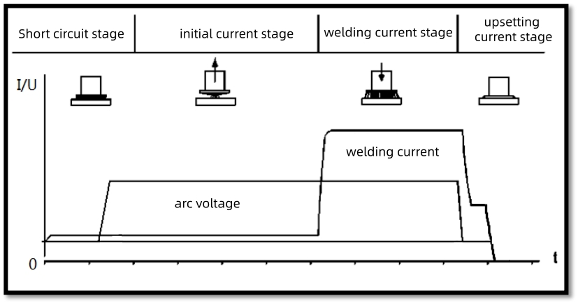
The electrical welding process of short-cycle drawn arc stud welding can be divided into four core stages: short-circuit stage, pilot arc striking stage, main arc welding stage and forging forming stage. Each welding stage is equipped with exclusive corresponding process parameters. These parameters are not independent of each other but have strong coupling correlations, which jointly determine the welding heat input and weld pool forming state, and ultimately directly affect the forming quality and comprehensive mechanical properties of welding joints.
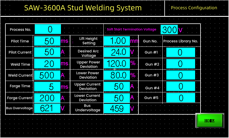
Combined with the official technical manuals and process specifications of mainstream equipment brands such as Hongbai SAW-3600 series, PIDS series and Tucker, this paper systematically sorts out and summarizes the core parameter system of short-cycle drawn arc stud welding, as shown in the table below.
|
Parameter Group
|
Parameter Name
|
Physical Significance / Functional Effect
|
Typical Range
|
Commissioning Priority
|
|---|---|---|---|---|
|
Arc Striking Parameters |
Pilot Current |
Generates a stable low-current arc to remove oil contamination and galvanized layers on the workpiece surface and establish a conductive path. |
20-50 A |
Secondary |
|
Pilot Time |
Duration of the pilot arc, which ensures stable arc root and completes surface cleaning. |
10-55 ms |
Secondary |
|
|
Energy Parameters |
Weld Current |
The dominant factor determining welding heat input, which directly affects the weld penetration and nugget size. |
100-2000 A |
Primary |
|
Weld Time
|
Duration of the main welding arc. Together with welding current, it determines the total welding energy (I²t). |
5-100 ms |
Primary |
|
|
Forging Parameters |
Plunge Current |
A low current applied after the stud plunges into the weld pool, which slows down weld pool cooling, relieves residual stress and prevents shrinkage cavities. |
100-300 A |
Secondary |
|
Plunge Time |
Duration for maintaining the forging current, which determines the tempering effect of the welded joint. |
2-12 ms |
Secondary |
|
|
Mechanical & Monitoring Parameters |
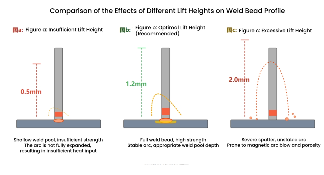
Lift Height |
The distance that the stud lifts off the workpiece surface, directly determining the main arc voltage. A larger lift height results in higher arc voltage and longer arc length. |
0.5-2.0 mm |
Primary |
|
Desired Arc Voltage |
A preset target value for welding quality monitoring and real-time energy compensation during welding. |
20-28 V |
Monitoring |
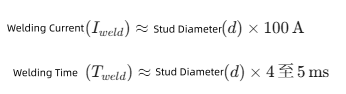
For novice technicians engaged in process commissioning, the configuration of reasonable and reliable initial process parameters serves as the prerequisite for successful debugging. A variety of industrial technical documents, including the Hongbai SAW-3600 equipment manual, official Emhart training materials, and Fundamentals of Stud Welding, provide empirical formulas for parameter setting. Although these formulas differ slightly in details, they share a consistent core design logic.
The initial parameter calibration based on welding current and welding time is the lowest-cost and most efficient method for preliminary process setting, which can quickly establish an effective welding process window.
- The pilot current is set to 40 A (default value for automatic welding guns),and the pilot time is 8-10 ms
- The initial welding current is calculated as I_weld = 8 × 100 = 800 A
- The initial welding time is calculated as T_weld = 8 × 4 = 32 ms
- The forging time is set to 6-8 ms
- The lift height is approximately 1.2 mm
1.2 Mechanical Parameter: Lift Height
2. Systematic Commissioning Procedure and Process Window Optimization
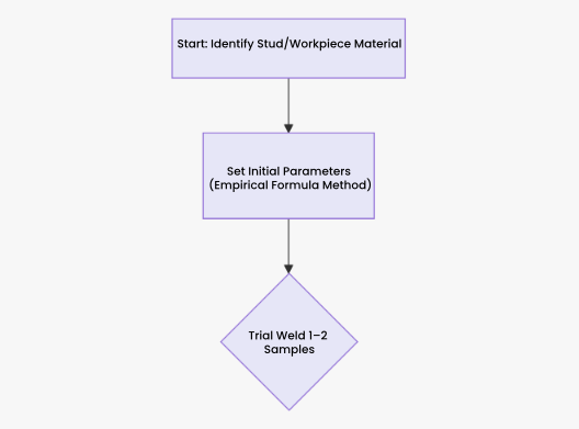
In practical applications, workpiece material, surface condition, and grounding configuration vary significantly. Empirical formulas only provide an initial reference for a safe process range. It is therefore necessary to proceed to the parameter fine-tuning stage, with the core objective of identifying a stable and reliable process window.
2.1 Step 1: Stepwise Approximation via Single-Factor Method
Commissioning Rule: Adjust only one parameter at a time while observing and evaluating the welding result. This avoids misinterpretation caused by multi-variable coupling.
Optimization Path 1 – Current Priority:
- Insufficient current: The fusion ring around the weld is narrow, and the stud detaches easily under minor force.
- Optimal current: The deposited metal forms a regular ring with full weld penetration. During torque or tensile testing, fracture occurs in the stud base material rather than at the weld (determined as the optimal state).
- Excessive current: Severe spatter occurs, potentially leading to workpiece burn-through and excessively deep weld penetration.
- Procedure: Keep the initial welding time and lift height unchanged, and adjust the welding current incrementally in steps of ±30~50 A.
- Evaluation criteria: As described above.
Optimization Path 2 – Time Fine-Tuning:
- Procedure: After determining the optimal current, fine-tune the welding time in steps of 1–2 ms.
- Purpose: Precisely control the total heat input while maintaining sufficient current. Avoid reducing heat input by drastically lowering the current when the current is already too high, as this can cause the weld pool to solidify too slowly and compromise joint quality.
2.2 Step 2: Finding the Energy Balance Window
Welding energy (defined as E=(I*I)×t/k, where I= current,t= time, and k= correction factor) is the key factor determining joint strength. The commissioning process must identify the stable feasible window between the lower energy limit (cold joint defect) and the upper energy limit (overburn defect).
The following is a conceptual diagram of the process window, developed based on Analysis of Defect Criteria and Solutions for Stud Welding and the quality control logic of major equipment manufacturers.
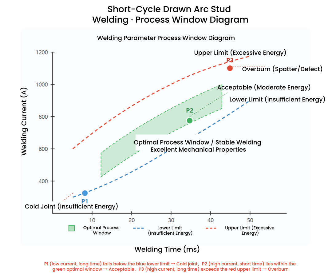
Commissioning Objective: Within the process window, prioritize parameter combinations featuring high current + short welding time. This aligns perfectly with the core characteristics of short-cycle drawn arc stud welding: concentrated heat input, minimal heat-affected zone, low workpiece distortion, making it particularly suitable for thin-plate applications.
2.3 Special Condition Commissioning: Galvanized and Thin-Plate Welding
The technical document Solutions to Burn-Through Issues in Stud Welding of 0.7mm Galvanized Steel Sheets provides an excellent reference case for commissioning.
| Parameter Item | Original Value (Mild Steel Plate) | Optimized Value (Galvanized / Thin Plate) | Reason for Adjustment |
|---|---|---|---|
| Welding Current | 650 A | 580–620 A | Reduce heat input to prevent burn-through of the galvanized layer. |
| Welding Time | 30 ms | 22–26 ms | Shorten heating duration to minimize heat accumulation. |
| Pilot Current | 28 A | Maintain at 28 A | Maintain pilot current while extending pilot time to enhance cleaning of oil contamination and coating. |
| Pilot Time | 55 ms | Maintain at 55 ms | Extend arc initiation duration to ensure stable arc ignition. |
- Pilot arc stage: For galvanized plates, the pilot time shall not be reduced, and shall be extended when necessary.
- Welding energy: Adopt the strategy of slightly reducing current and prioritizing shorter welding time, so that the arc acts on and leaves the weld pool rapidly.
- Forging stage: Maintain sufficient forging time to cool the weld pool under compression and prevent porosity.
3. Root Cause Analysis of Faults and Parameter Adjustment
3.1 Correspondence between Common Defects and Parameters
| Defect Phenomenon | Root Cause | Commissioning Countermeasure |
|---|---|---|
|
Incomplete Fusion
|
1. Insufficient heat input 2. Improper lift height (too low or too high) 3. Excessively thick base plate |
1. Increase welding current or welding time 2. Set the lift height to 1.5 times the plate thickness 3. Increase forging force |
| Porosity | 1. Insufficient shielding gas (for aluminum welding) or premature gas cut-off 2. Residual oil contamination or zinc coating on workpiece surface 3. Excessively fast cooling of weld pool |
1. Increase shielding gas flow rate or extend post-flow duration 2. Raise pilot current or prolong pilot time 3. Extend forging time for slow cooling |
| Spatter | 1. Excessive welding energy (over-high current or over-long welding time) 2. Excessively large lift height 3. Delayed or slow forging action |
1. Reduce welding current or welding time 2. Decrease lift height 3. Adjust the advance descent time of the welding gun to speed up stud insertion |
| Weld Deviation / Stud Tilting | 1. Welding gun not perpendicular to the workpiece 2. Misaligned stud inside the collet 3. Magnetic blow caused by poor grounding |
1. Calibrate the perpendicularity of welding gun (angular deviation < 1°) 2. Replace or clean the contact tip 3. Add more ground cables and optimize grounding positions |
3.2 Real-time Monitoring and Diagnosis
Modern welding machines (e.g., Hongbai PIDS, Hongbai SAW-3600R and Tucker DCE) are equipped with waveform recording and welding quality monitoring functions. Professional commissioning requires the ability to analyze welding waveforms.
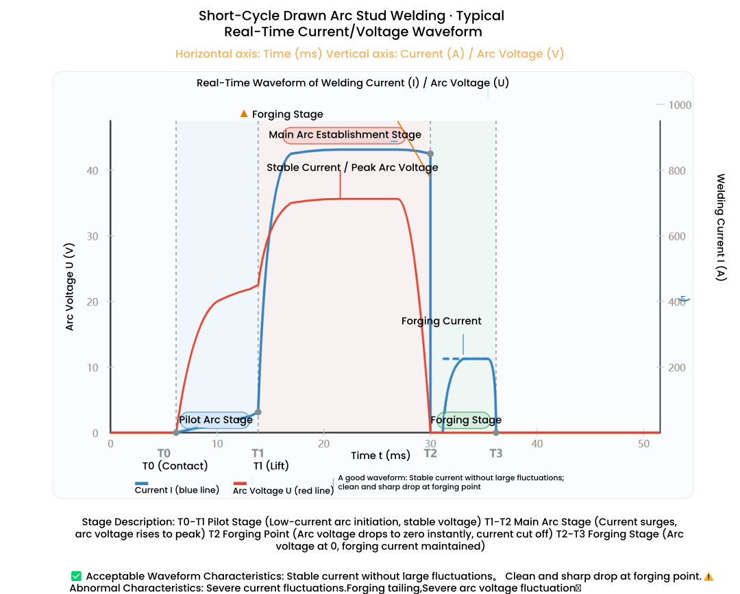
Commissioning Application
If the descent at point T2 occurs too early (the arc fails to burn sufficiently), it indicates insufficient welding time or inadequate lift height, both of which need to be increased.
If the arc voltage drops slowly from T2 to T3 (arc trailing), it means the forging action is delayed or the insertion depth is insufficient. Adjust the mechanical descent time of the welding gun accordingly.
4. Advanced Skills and Experience Summary
4.1 Power Deviation and Energy Compensation
4.2 Summary of Standard Operation Procedures