
In automotive manufacturing, home appliance production, and precision equipment assembly, stud welding has become an indispensable joining process, valued for its high efficiency, reliability, and minimal thermal impact on the base material.
Among its variants, short-cycle drawn-arc stud welding (SC) stands out for its rapid welding speed, precise heat input, and adaptability to thin-sheet and coated materials, making it a cornerstone technology in body-in-white (BIW) fabrication and subassembly production.
Yet, maintaining consistent weld quality remains a persistent challenge. Defects such as spatter, cold welds (lack of fusion), porosity, and burn-through not only impair surface appearance but can also lead to functional failures.
This article, grounded in the technical principles of leading systems—including those from Hongbai Technology and Emhart—provides an in-depth analysis of the process adjustment techniques for short-cycle drawn-arc stud welding. It is intended to offer a systematic, shop-floor-ready quality assurance framework for welding engineers and field technicians.
1. Process Principle and Core Parameters of Short‑Cycle Drawn‑Arc Stud Welding
1.1 Operating Principle and Sequence Control
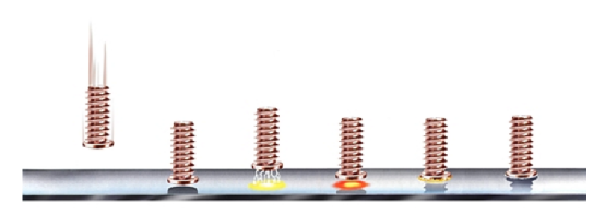
Short‑cycle drawn‑arc welding differs fundamentally from long‑cycle or capacitor‑discharge stud welding. Its essence lies in the precise timing of a highly controlled sequence to achieve a sound joint within an extremely short weld cycle. The standard sequence comprises the following phases:
- Contact Phase (Stud on Workpiece – SOW): The stud tip contacts the workpiece perpendicularly, closing the welding circuit. The system detects the SOW signal to initiate the cycle.
- Pilot Arc Phase: A low pilot current (typically ≈30 A) is applied while the linear motor (LM) rapidly lifts the stud to a preset height, striking a stable arc. This step removes surface contaminants (oil, oxides) to ensure stable main‑arc ignition.
- Main Arc Phase: Upon successful pilot arc establishment, the system instantly switches to the main welding current—ranging from several hundred to over a thousand amperes. The high‑energy arc rapidly melts both the stud tip and the workpiece surface, creating a dynamic molten pool. This phase is critical to joint formation, and the settings of welding current and weld time are of paramount importance.
- Plunge Phase: At a precisely controlled moment before arc extinction, the linear motor reverses (or spring force acts) to drive the stud into the molten pool at a controlled speed. The arc extinguishes, and the molten metal solidifies rapidly, forming a robust joint.
In this process, welding current, weld time, lift height, and stud extension constitute the four primary parameters that determine weld quality. The ability to fine‑tune these parameters based on actual production conditions is the hallmark of a skilled technician.
1.2 Parameter Calculation and Adjustment Principles
Welding Current (Iw) and Weld Time (Tw): Together they define the heat input.
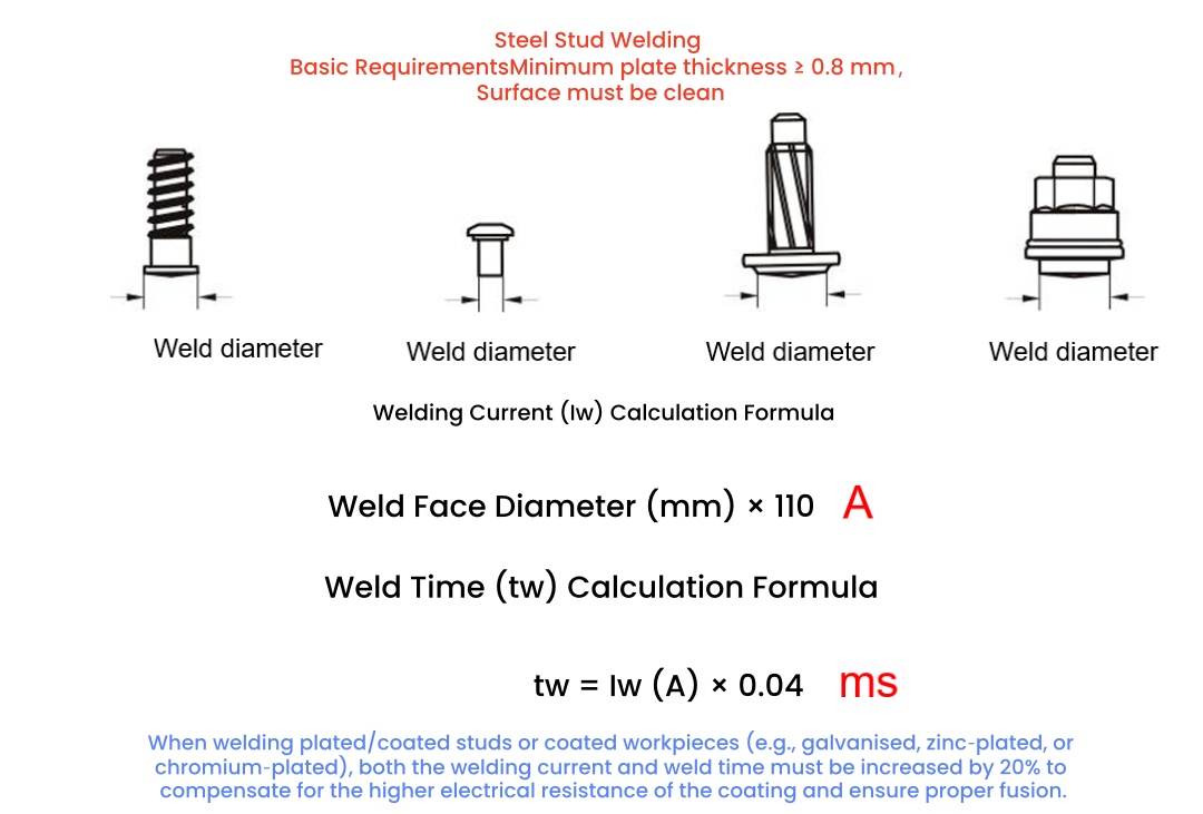
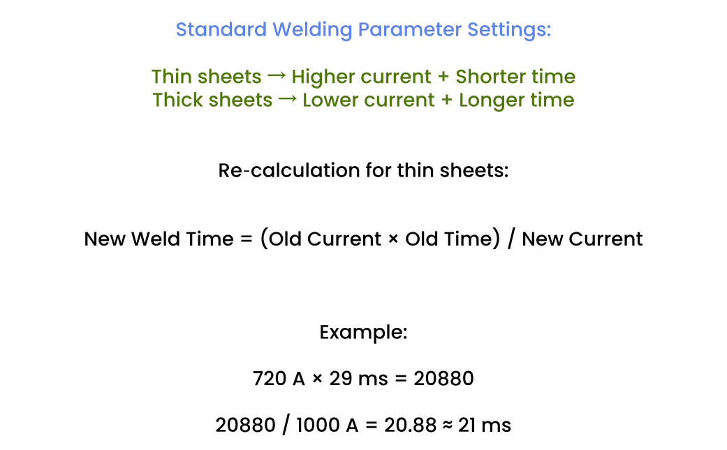
This provides an initial setpoint.The general adjustment rule is: Thin sheets → higher current, shorter time; Thick sheets → lower current, longer time.For re-calculation, a practical approach is: New Time = (Old Current × Old Time) / New Current.
Waveform Control and Adaptive Features: Modern stud welders offer sophisticated waveform control. Arc voltage is a key in-process indicator of joint quality.On galvanised sheets, a pilot arc voltage of 16–22 V typically indicates a clean surface; readings above 28 V often signal surface contamination or incorrect parameters (e.g., excessive lift height).Advanced systems can automatically adjust welding current or time in a closed-loop manner, based on the deviation between actual and set arc voltage, with adjustment ranges up to 50% – this is the core mechanism for ensuring batch-to-batch consistency.
2. Practical Process Tuning – Hands-On Adjustment Techniques
Precise parameter settings must be translated into physical adjustments of the equipment and tooling.
2.1 Fine-Adjusting Lift Height
Lift height determines arc length and energy distribution. Too high: arc instability and increased magnetic blow-out. Too low: concentrated energy, risk of burn-through and spatter.
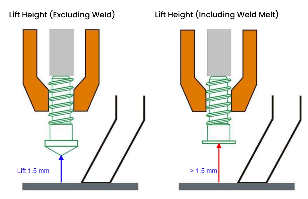
Adjustment method: For solenoid-lift guns, open the rear cover – there is typically a stepped adjustment dial (0.5 mm per step). Rotate it counter-clockwise from zero to the desired value.For servo-controlled guns, set the lift stroke precisely via the teach pendant or controller parameters.Recommended range: 1.2–1.5 mm (adjust according to stud diameter).
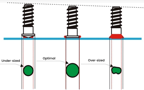
2.2 Precision Setting of Stud Extension
Stud extension (also called stick-out) is the distance from the stud tip (or flange face) to the front face of the anti-spatter sleeve or support rod. It directly affects the stud’s contact geometry and its plunge path into the molten pool.
Adjustment method:
- Loosen the locking screw on the support rod or anti-spatter sleeve.
- Place the gun vertically on a flat reference plate, ensuring the stud tip contacts the plate.
- Slide the support rod/sleeve until the gap between its face and the stud tip equals the desired extension.
- Key rule: The stud must protrude at least 2 mm beyond the sleeve; the recommended range is 2–3 mm. Excessive extension can cause stud bending and affect perpendicularity; insufficient extension impairs arc formation and pool development.After adjustment, tighten the locking screw. In automatic/semi-automatic modes, always verify the extension using a calibration (teaching) routine; deviation must be within ±0.1 mm.
3. The Four “Gatekeepers” of Weld Quality – A Comprehensive Analysis
The final quality of short-cycle drawn-arc stud welding is the outcome of a systematic engineering approach. While parameter optimisation is fundamental, consistent physical adjustments and proper grounding are the bridges that make it achievable.The following four areas are examined in detail: contact tip, stud extension, support rod, and grounding standards.
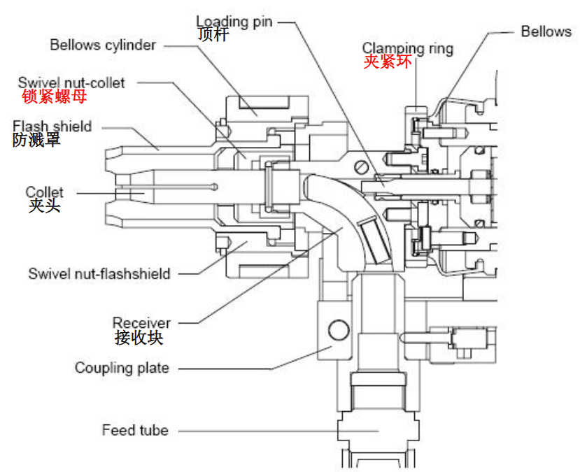
3.1 Meticulous Maintenance of the Contact Tip – The Precision Energy Conductor
The contact tip (or collet) is the final link in conducting current and positioning the stud.
Key technical concerns and risks:
Conductivity and wear: Tip wear and slag accumulation increase loop resistance, leading to cold welds, incomplete fusion, or even arcing that damages the collet.
Concentricity and clamping force: A non-concentric or worn tip causes stud tilting, affecting perpendicularity; insufficient clamping force allows the stud to shift during welding, disturbing the molten pool.
Process assurance requirements:
Daily cleaning: Before each shift, remove internal/external slag with dedicated tools and blow clean with compressed air.
Wear inspection: Regularly (every shift/week) check the inner diameter for enlargement. Replace immediately when weld quality fluctuates (e.g., difficult stud release or unstable clamping).Per Hongbai’s maintenance guidelines, replace immediately if the wear exceeds 0.1 mm.
Secure locking:Always tighten the lock nut with the specified spanner. Loose connections can cause arcing between the tip and receiver, damaging front-end components and losing perpendicular reference.
Loading practice: When loading a stud, the plunger should push it 3–6 mm beyond the tip (adjust according to stud length) to avoid damaging the collet.
3.2 Dynamic Control of Stud Extension – The Physical Foundation of Pool Formation
In short-cycle welding, the effective extension (typically 2–3 mm) directly determines arc establishment and the available space for pool formation.
Technical key points:
Dynamic impedance: Extension affects the static reactance of the welding circuit.
Electromagnetic interference and magnetic blow-out: Incorrect extension exacerbates blow-out, causing one-sided lack of fusion.
Process assurance requirements:
Gauge verification: Use dedicated setting gauges for each stud type to regularly verify the effective extension distance. This is a prerequisite for stable welding.
Adaptive compensation: During continuous robotic welding, the support rod face may wear or accumulate spatter, altering the effective extension. Set up automatic or periodic calibration routines (using the gun’s “teaching” procedure on a flat plate) to correct the actual extension.
Coordination with lift height: Ensure that the extension is greater than the required penetration depth to provide sufficient space for the stud to plunge into the pool.
3.3 Precision Adjustment of the Support Rod – The Cornerstone of Stability and Symmetry
The support rod (often integrated into the weld head on automatic guns) ensures perpendicularity and provides reaction force during welding. Its adjustment has a direct impact on final weld quality.
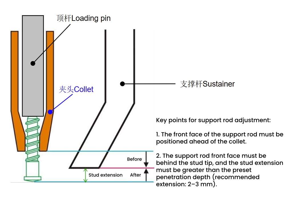
Adjustment procedure:
Initial positioning: Place the gun, with the correct collet and loaded stud, gently on a flat plate.
Set the gap: Loosen the support rod locking screw and slide it until the gap between its front face and the stud tip equals the required extension (2–3 mm).
Concentricity check: Before tightening, visually or with a concentricity tool, verify that the stud is centred within the support rod/ceramic ferrule. If off-centre, adjust the set screws on the support rod base until perfectly aligned.
Process assurance:
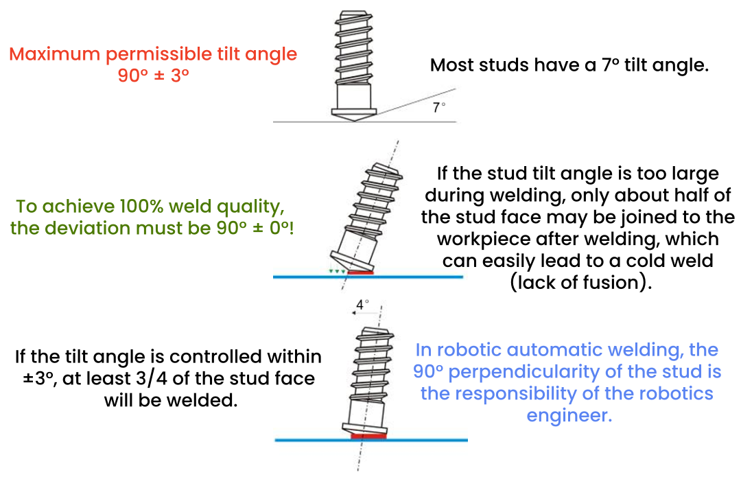
Perpendicularity monitoring: After installing the support rod, the gun’s geometric alignment is critical. Some guns feature an angle sensor.
To adjust: place the gun vertically on a plate (with stud loaded), unscrew the adjustment screw until the vertical indicator lamp turns off; then screw in until the lamp lights up. Verify with test welds.
Splash guard management: The anti-spatter sleeve (manual guns) or support rod (automatic guns) must always be positioned between the collet and the workpiece. Never allow the collet to contact the workpiece without a stud loaded – this will cause misfiring. Any loosening must be immediately re-adjusted and recalibrated.
3.4 Grounding Design for Stud Welding Fixtures – Eliminating the Root Cause of Magnetic Blow-Out
Magnetic blow-out is one of the most common and difficult-to-diagnose defects in stud welding, often manifesting as one-sided incomplete fusion or an irregular fillet. Its root cause is uneven current distribution in the welding circuit.Therefore, proper grounding design is a critical (and often overlooked) process standard in fixture engineering.
Core Technologies and Design Standards
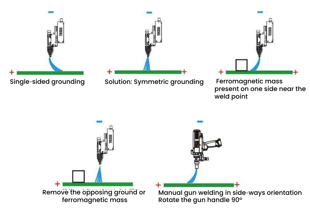
Shortest-path and symmetry principles: Place the ground clamp as close as possible to the weld point (the centre of the circuit between the gun and workpiece) and ensure magnetic symmetry on both sides of the workpiece.Best practice: Use multiple ground connections or a parallel grounding busbar at a single station. This allows welding current to return evenly from all directions, eliminating arc deflection caused by asymmetric magnetic fields.
Dual sensing-line system: Modern high-end stud welders (e.g., Hongbai, Emhart) employ independent voltage sensing lines that do not share the main welding current path. They connect directly to the workpiece as close as possible to the weld, providing the control system with a true arc-voltage signal.Requirement: Total resistance of the ground and sensing lines must be extremely low (recommended: ground cable ≥ 50 mm², sensing cable ≥ 1.5 mm²). The sensing-line take-off point should be on the opposite side of the weld from the main ground clamp, creating a perfectly symmetrical four-wire (Kelvin) configuration.
Workpiece material and tooling: All positioning fixtures (e.g., bushing guides) must be made of non-magnetic materials (copper, brass, aluminium alloys) to prevent them from becoming “magnetic sinks” that distort the arc.Fixtures must rigidly support the workpiece to prevent vibration during welding, which could disturb pool solidification and cause cracks.
Process design checklist:
- Is the ground clamp arranged symmetrically around the weld?
- Is an independent sensing line used, and is its contact resistance acceptable?
- Are there any ferromagnetic obstructions (e.g., steel shims, rusty platens) in the circuit?
- Is the ground connection clean, firm, and capable of carrying high currents without melting or marking the workpiece?
- Is there a schedule for daily/weekly inspection and maintenance of ground cables?
Conclusion – Closing the Quality Assurance Loop
Short-cycle drawn-arc stud welding, though highly automated and intelligent, ultimately depends on the engineer’s deep understanding of fundamental physics and the rigorous matching of every process parameter with the physical hardware.From micrometre-scale wear on the contact tip, to micron-level adjustment of stud extension, to absolute concentricity of the support rod, and to symmetrical grounding design in fixtures – each link is interconnected.From the detailed analysis above, combined with fault-diagnosis logic, we can summarise the core quality-assurance loop as:
- Precise energy delivery – via the contact tip and correctly tuned parameters.
- Absolute spatial stability – ensured by the support rod, extension, and perpendicularity.
- Symmetric circuit balance – rooted in scientific grounding and sensing-line layout.
When facing production issues, welding engineers should not blindly adjust primary parameters (current/time) alone. Instead, they should follow this analytical framework – first inspecting the physical setup.Only when every “detail” meets the standard can we truly master short-cycle drawn-arc stud welding, making it the most reliable “industrial fastener” on the production line, leaving perfect weld marks on every body-in-white and precision component.