自公司成立以来
公司员工
企业土地面积
服务客户
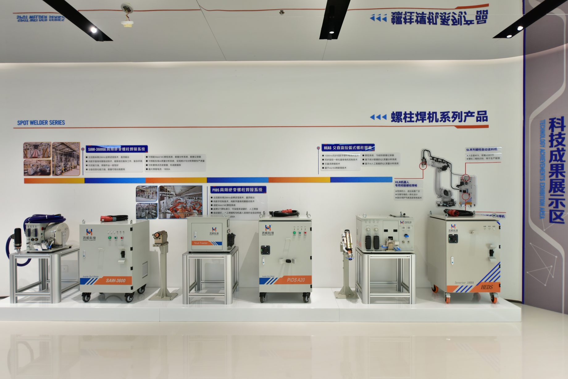
新一代•新技术•新工艺
新技术优势:
100KHz同步纯数字硬件电流环技术;
同步驱动与控制一体化直线电机控制技术;
交直流焊接技术;
基于4G/5G物联网技术;
群控系统,TB级数据记录仪;
基于统计数据的QC质量分析系统;
基于AI人工智能的QC质量分析系统;

公司规模介绍
公司视创新为根本,持续投入巨资发展壮大研发团队,致力于打造行业领先的研发中心。公司现有员工近500人,其中研发人员30%,年均研发费用占销售收入的15%以上。公司不仅完成了国家重点科技攻关项目和国家火炬计划项目,还成功研发了一批创新产品,并获得了100多项国际国内专利和软件著作权。
我们的产品
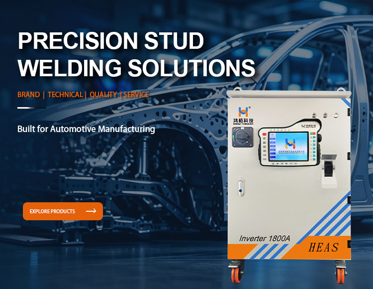
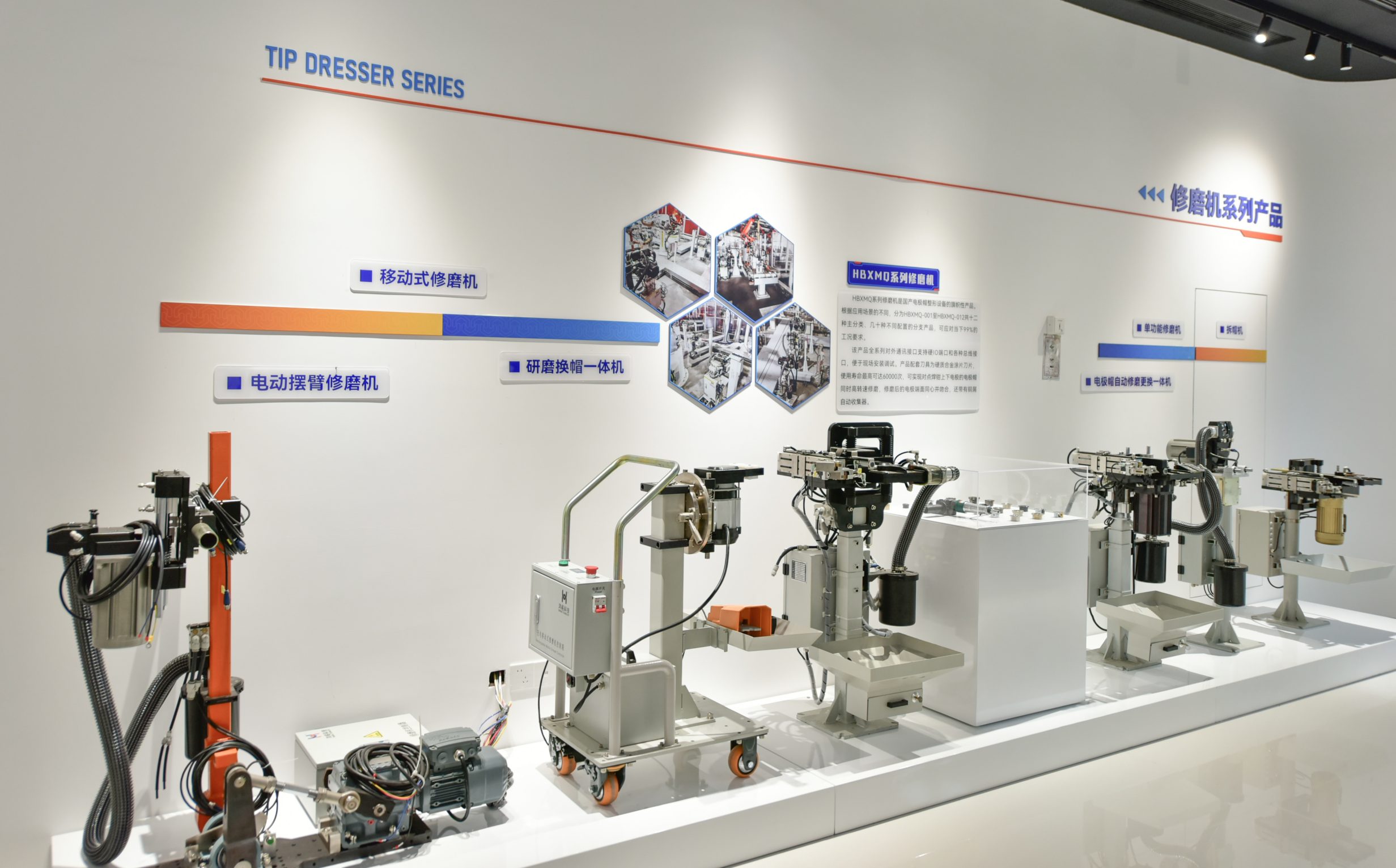
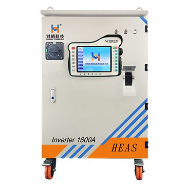
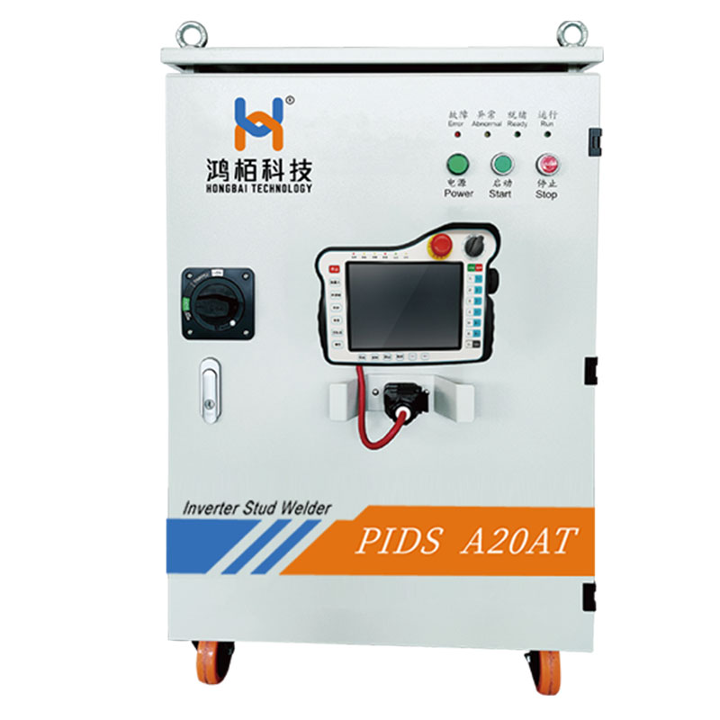
公司自2003年进入汽车智能焊接设备领域以来,业务范围不断拓展,包括车身螺柱焊接设备及工作站、点焊设备及工作站、磨床系列等。
该公司是国家高新技术企业,专注于细分市场、拥有尖端技术的“小巨人”企业,承担国家重点科技攻关项目,拥有省级工程技术研究中心。
打破国际垄断,螺柱焊机国内市场占有率最高,服务于特斯拉、比亚迪等30多家主流汽车厂商及零部件供应商。
研发人员占比30%,年均研发投入超过收入的15%,累计获得国际/国内专利及软件著作权100余项,实现核心技术的自主掌控。
拥有45000平方米的现代化生产基地(广东、安徽),具备规模化智能制造和柔性化生产能力。
形成从研发设计、生产制造到销售服务的闭环,保证了供应链的安全性和响应效率。
涵盖智能汽车焊接设备、工业自动化、智能家居三大高增长领域,形成产业协同效应。
13
2026 - 10
Aluminum welding is not just about increasing current With the rapid development of electric vehicles (EVs) and lightweight automotive structures, aluminum has become increasingly important in Body-in-White (BIW) manufacturing. However, welding aluminum is fundamentally different from welding steel. Many manufacturers find that a conventional DC stud welding system can achieve stable results on steel studs but struggles when applied to aluminum components. Problems such as unstable arc behavior, porosity, insufficient fusion, and low pull strength often occur. The reason is not simply insufficient welding current. The real challenge comes from the unique physical properties of aluminum: High thermal conductivity Low melting temperature High melting point oxide layer Rapid heat dissipation These characteristics determine that aluminum stud welding requires more precise control of heat input and current direction. This is why advanced AC/DC stud welding technology has become an important solution for aluminum automotive applications. Aluminum vs Steel: Why the Welding Process Is Completely Different Although aluminum and steel can both be joined through arc welding, their melting behavior is very different. Property Steel Aluminum Impact on Welding Melting point Approx. 1500℃ Approx. 660℃ Aluminum melts much earlier Oxide layer Thin oxide film Al₂O₃ oxide layer, melting point approx. 2050℃ Oxide layer is difficult to break Thermal conductivity Approx. 50 W/(m·K) Approx. 237 W/(m·K) Heat dissipates much faster Density 7.8 g/cm³ 2.7 g/cm³ Lightweight structure advantage Molten pool stability Relatively stable Difficult to maintain Requires precise heat control The biggest challenge is the aluminum oxide layer. Although aluminum itself melts at around 660℃, the aluminum oxide layer on the surface requires temperatures above 2000℃ to break down. This means: Before the aluminum base material can melt properly, the oxide layer must first be effectively removed. Without breaking this barrier, the stud and base material cannot form a strong metallurgical bond. Why…
09
2026 - 10
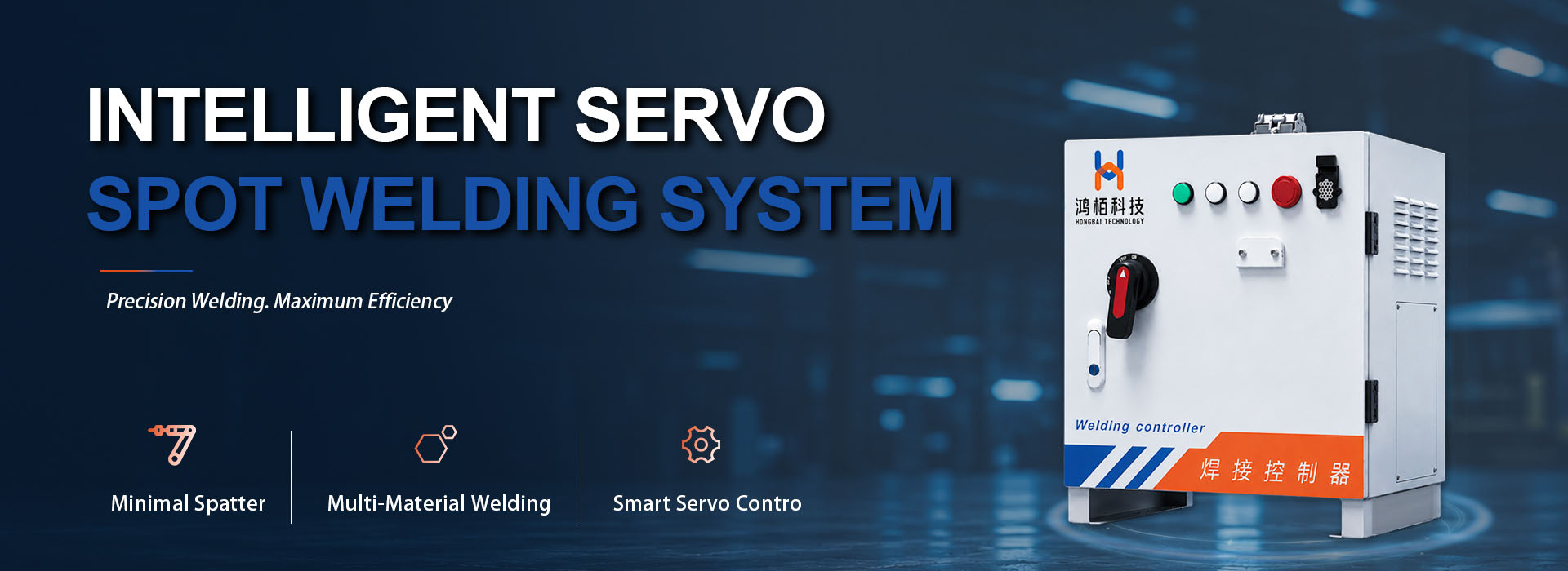
In resistance spot welding, a stable weld is not simply a matter of setting the correct current. The result depends on how welding current, electrode force, and weld time interact throughout the welding cycle. This becomes particularly important in automotive manufacturing, where a single production line may handle different sheet thicknesses, galvanized steels, and high-strength materials. A welding schedule that performs well on one material combination may produce excessive spatter or insufficient weld nugget formation on another. Increasing the current is not always the answer. Nor does applying more electrode force necessarily improve the weld. What matters is maintaining the right relationship between electrical heat generation and the mechanical conditions at the joint. This is the principle behind dual-loop control in resistance spot welding. By regulating welding current and electrode force through coordinated feedback control, the system can respond more effectively to process variations and help maintain consistent welding performance. How Dual-Loop Control Works Dual-loop control refers to two feedback control functions operating within the welding system: closed-loop welding current control and weld force control. Although they serve different purposes, both influence the conditions under which the weld nugget forms. Control function Feedback or monitoring variable Control mechanism Primary objective Welding current control Actual welding current Inverter output regulation Maintain the commanded current despite electrical load variations Weld force control Electrode force, where sensor feedback is available Pneumatic proportional valve or electric servo actuator Regulate electrode force and monitor force-related process conditions Adaptive coordination Application-specific process feedback and programmed welding schedules Control logic and parameter adjustment Match welding conditions to qualified material and joint requirements The current control loop monitors the actual welding current and compares it with the programmed target. The controller adjusts the inverter output to reduce deviations, helping maintain the required current as electrical conditions change. The…
30
2026 - 09
The weld cycle is complete. The stud looks properly welded, and the welding system shows no obvious alarm. Then, during assembly or a pull test, the weld stud breaks away from the workpiece. For engineers responsible for welding quality, this is a familiar but frustrating situation. The first reaction is often to increase the welding current or extend the weld time. Sometimes that changes the result. But if the actual cause lies in stud positioning, grounding, surface condition, feeding stability, or process repeatability, changing the welding parameters alone may only move the problem from one place to another. A more reliable approach is to look at the complete welding process and determine where the weld started to lose stability. 02|Start With the Failed Weld Before changing any welding parameters, start with the failed weld itself. The fracture surface can provide useful evidence about how the weld was formed. Little visible fusion may point toward insufficient heat input or unstable arc conditions. Uneven fusion around the stud may indicate problems with gun alignment, stud positioning, grounding, or surface condition. It is also important to distinguish between a stud that never achieved sufficient fusion and one that formed a weld but later failed under mechanical loading. These two situations may look similar from the outside, but they require different troubleshooting approaches. Cross-section analysis can reveal the difference between proper fusion, partial fusion, and lack of fusion in stud welding. The first question should therefore be: What does the failed weld tell us about how the weld was formed? Observed Condition Possible Direction of Investigation Little or no visible fusion Welding current, weld time, lift height, arc stability Uneven fusion around the stud Gun alignment, stud positioning, grounding Excessive spatter Heat input, arc conditions, parameter combination Weld looks acceptable but stud pulls off…
21
2026 - 09
In automated stud welding, manufacturers naturally focus on the welding power source, weld gun, and robot. Welding current, weld time, positioning accuracy, and robot speed are all critical parameters. Yet when a system moves into continuous production, another factor often has a much greater impact on the actual production cycle than expected: how reliably the next stud is prepared for welding. A complete automated stud welding cycle involves much more than the welding operation itself. The stud must be separated, conveyed, positioned, loaded into the weld gun, and finally welded. If the feeding process is delayed or interrupted, the welding system and robot may have to wait, regardless of how fast the welding process itself can run. This is why the feeding system should not be treated simply as an accessory to a stud welding machine. In a high-volume production environment, it is part of the process that determines whether the entire welding cycle can continue smoothly. The goal of an automatic stud feeding system is not simply to feed a stud. It is to make sure the right stud is ready, in the right position, at the right time. 01 | When Welding Is Fast, Why Can Production Throughput Still Fall Short? When evaluating an automated stud welding system, welding time is usually one of the first parameters engineers consider. However, high performance at the welding stage does not automatically translate into high production throughput. The reason is that the actual production cycle includes several operations before the weld is made: Stud Separation → Feeding → Stud Positioning → Gun Loading → Robot Positioning → Welding Once one stud has been welded, the robot is ready to move to the next weld location. At the same time, the next stud needs to be prepared. If the robot reaches the…
18
2026 - 09
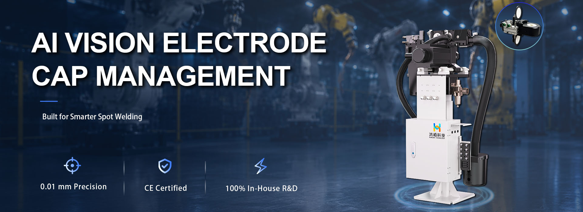
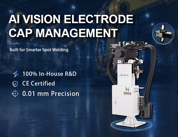
In Body-in-White (BIW) production, electrode cap dressing may seem like a relatively small operation. In practice, however, it has a direct connection with electrode cap life, weld consistency, production cycle time, and maintenance cost. Many problems on the shop floor do not start with a failure of the electrode dresser itself. They often develop gradually from the cutter: an unsuitable cutter selection, a mismatch between the cutter and dressing parameters, or continued use after the cutting edge has worn. The result may eventually appear as an abnormal electrode face, inconsistent dressing, or changes in weld quality. From our experience with electrode cap dressing applications, we believe that an electrode dressing cutter should not be selected based only on purchase price or theoretical tool life. The cutter, electrode cap, dressing machine, and process parameters need to work as one matched system. This is one of the key factors we consider when developing electrode cap dressing solutions. 1. Why Does an Electrode Dressing Cutter Affect Weld Quality? After continuous welding, the electrode cap gradually develops wear, deformation, and material buildup on its working face. If the electrode cap is not dressed at the appropriate interval, its geometry changes. This can affect the contact area and current density during resistance spot welding. The purpose of electrode cap dressing is not simply to “remove a layer” from the cap. The objective is to restore a stable: Electrode face diameter Face geometry Concentricity Surface condition Contact geometry The dressing cutter is the component that directly creates this geometry. When the cutter condition changes, the dressing result changes with it. For example, as a cutting edge becomes dull, the actual cutting condition may change even when spindle speed, dressing pressure, and dressing time remain unchanged. On the production line, this may appear as: Changes in electrode…
15
2026 - 09
In robotic spot welding, welding current often gets most of the attention. But current alone does not determine whether a weld will be stable. Welding force, electrode movement, response speed and force repeatability also directly influence the welding process. This becomes even more important when one welding gun needs to handle different sheet thicknesses or when aluminum is introduced into automotive body structures. This is where the actuator inside the welding gun matters. A hollow servo electric cylinder combines servo actuation, precision screw transmission and position/force control into a compact linear unit. For robotic spot welding, its role goes beyond simply opening and closing the electrodes. It provides the mechanical and control foundation for accurate welding-force management and adaptive coordination between welding force and welding current. 1. What Is a Hollow Servo Electric Cylinder? 1. 什么是空心伺服电动气缸? A hollow servo electric cylinder is a linear actuator designed to convert servo motor rotation into controlled linear motion. Unlike a conventional actuator consisting of a servo motor, reduction mechanism and separate screw transmission, a linear integrated electric cylinder can place the motor and screw mechanism on the same axis. This shortens the transmission path and creates a more compact mechanical structure. For a robotic spot welding gun, this design has several practical benefits. The actuator needs to operate within a limited installation envelope while repeatedly generating high welding force. At the same time, the gun must move quickly enough to meet the cycle time of an automated production line. A shorter mechanical transmission path can help reduce unnecessary transmission components and provide a more direct connection between servo motion and electrode movement. This is one reason why a hollow servo electric cylinder for spot welding is particularly suitable for applications where compact installation, mechanical stiffness and dynamic response are important. 2. Why Does…