2026-10-13
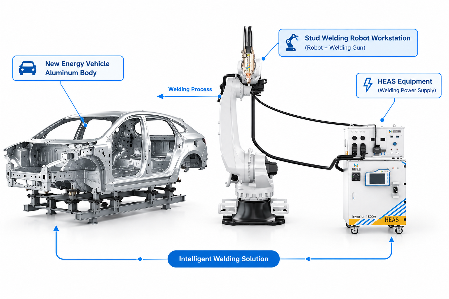
Aluminum welding is not just about increasing current With the rapid development of electric vehicles (EVs) and lightweight automotive structures, aluminum has become increasingly important in Body-in-White (BIW) manufacturing. However, welding aluminum is fundamentally different from welding steel. Many manufacturers find that a conventional DC stud welding system can achieve stable results on steel studs but struggles when applied to aluminum components. Problems such as unstable arc behavior, porosity, insufficient fusion, and low pull strength often occur. The reason is not simply insufficient welding current. The real challenge comes from the unique physical properties of aluminum: High thermal conductivity Low melting temperature High melting point oxide layer Rapid heat dissipation These characteristics determine that aluminum stud welding requires more precise control of heat input and current direction. This is why advanced AC/DC stud welding technology has become an important solution for aluminum automotive applications. Aluminum vs Steel: Why the Welding Process Is Completely Different Although aluminum and steel can both be joined through arc welding, their melting behavior is very different. Property Steel Aluminum Impact on Welding Melting point Approx. 1500℃ Approx. 660℃ Aluminum melts much earlier Oxide layer Thin oxide film Al₂O₃ oxide layer, melting point approx. 2050℃ Oxide layer is difficult to break Thermal conductivity Approx. 50 W/(m·K) Approx. 237 W/(m·K) Heat dissipates much faster Density 7.8 g/cm³ 2.7 g/cm³ Lightweight structure advantage Molten pool stability Relatively stable Difficult to maintain Requires precise heat control The biggest challenge is the aluminum oxide layer. Although aluminum itself melts at around 660℃, the aluminum oxide layer on the surface requires temperatures above 2000℃ to break down. This means: Before the aluminum base material can melt properly, the oxide layer must first be effectively removed. Without breaking this barrier, the stud and base material cannot form a strong metallurgical bond. Why…
2026-10-09
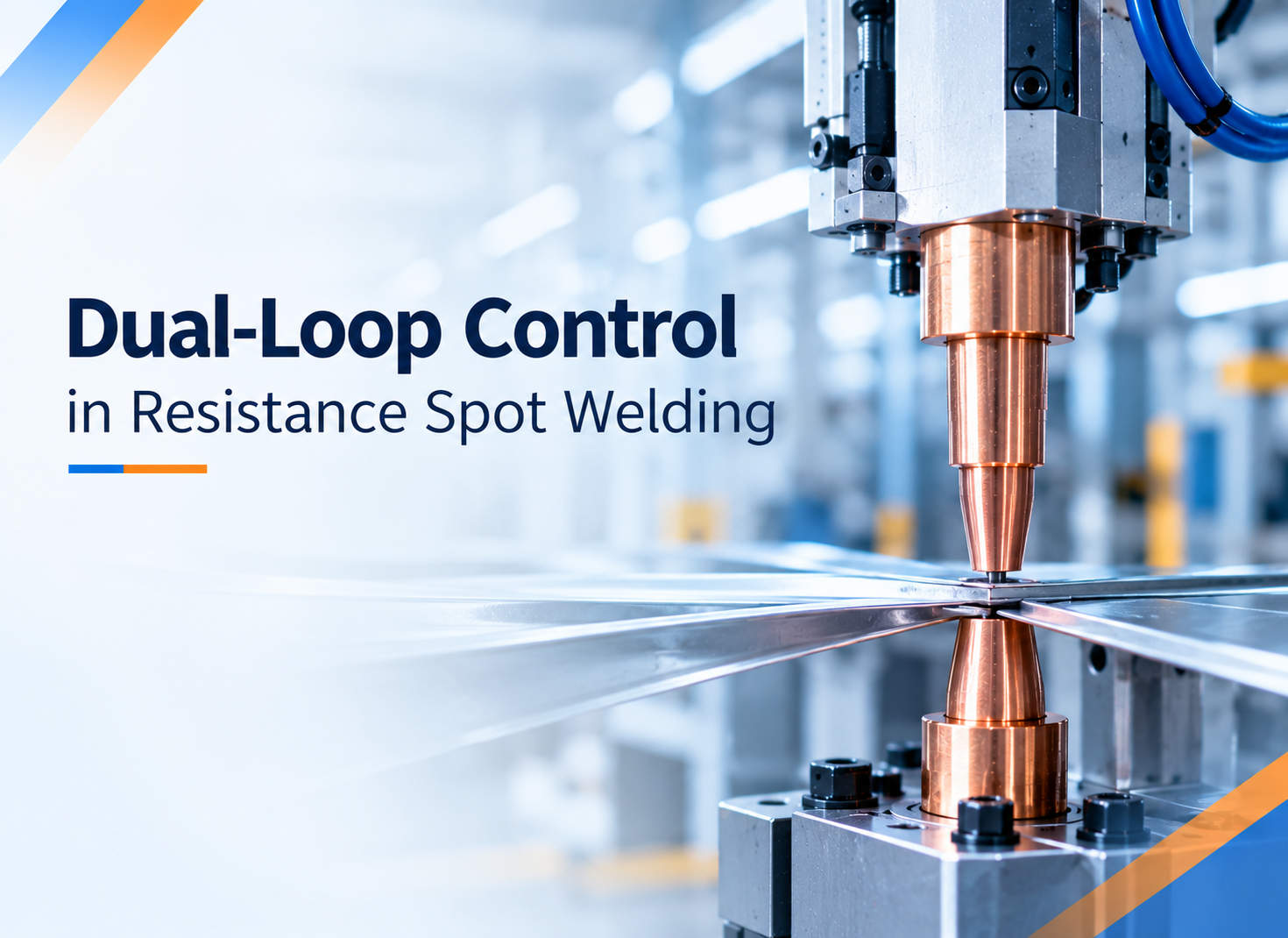
In resistance spot welding, a stable weld is not simply a matter of setting the correct current. The result depends on how welding current, electrode force, and weld time interact throughout the welding cycle. This becomes particularly important in automotive manufacturing, where a single production line may handle different sheet thicknesses, galvanized steels, and high-strength materials. A welding schedule that performs well on one material combination may produce excessive spatter or insufficient weld nugget formation on another. Increasing the current is not always the answer. Nor does applying more electrode force necessarily improve the weld. What matters is maintaining the right relationship between electrical heat generation and the mechanical conditions at the joint. This is the principle behind dual-loop control in resistance spot welding. By regulating welding current and electrode force through coordinated feedback control, the system can respond more effectively to process variations and help maintain consistent welding performance. How Dual-Loop Control Works Dual-loop control refers to two feedback control functions operating within the welding system: closed-loop welding current control and weld force control. Although they serve different purposes, both influence the conditions under which the weld nugget forms. Control function Feedback or monitoring variable Control mechanism Primary objective Welding current control Actual welding current Inverter output regulation Maintain the commanded current despite electrical load variations Weld force control Electrode force, where sensor feedback is available Pneumatic proportional valve or electric servo actuator Regulate electrode force and monitor force-related process conditions Adaptive coordination Application-specific process feedback and programmed welding schedules Control logic and parameter adjustment Match welding conditions to qualified material and joint requirements The current control loop monitors the actual welding current and compares it with the programmed target. The controller adjusts the inverter output to reduce deviations, helping maintain the required current as electrical conditions change. The…
2026-09-30
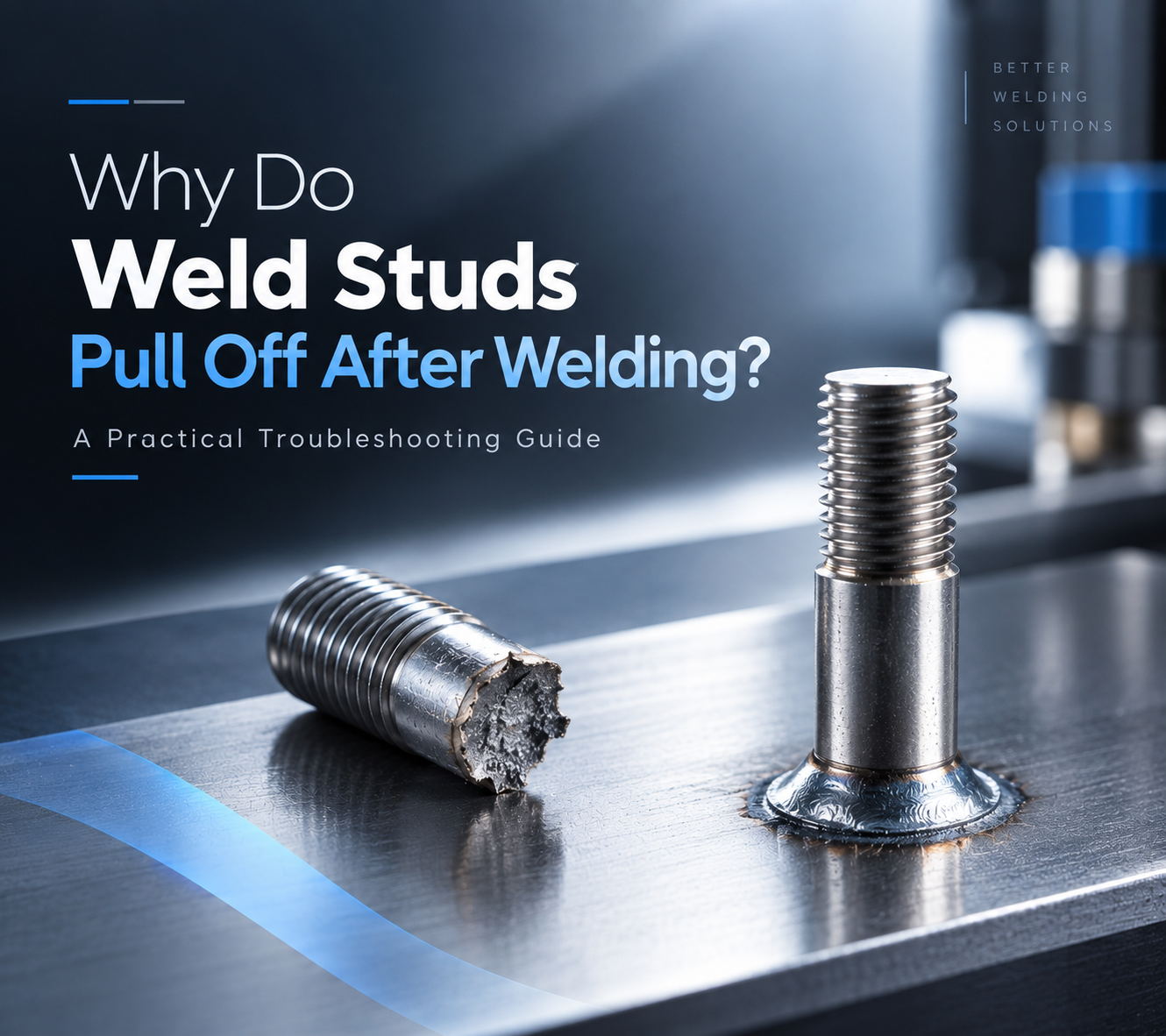
The weld cycle is complete. The stud looks properly welded, and the welding system shows no obvious alarm. Then, during assembly or a pull test, the weld stud breaks away from the workpiece. For engineers responsible for welding quality, this is a familiar but frustrating situation. The first reaction is often to increase the welding current or extend the weld time. Sometimes that changes the result. But if the actual cause lies in stud positioning, grounding, surface condition, feeding stability, or process repeatability, changing the welding parameters alone may only move the problem from one place to another. A more reliable approach is to look at the complete welding process and determine where the weld started to lose stability. 02|Start With the Failed Weld Before changing any welding parameters, start with the failed weld itself. The fracture surface can provide useful evidence about how the weld was formed. Little visible fusion may point toward insufficient heat input or unstable arc conditions. Uneven fusion around the stud may indicate problems with gun alignment, stud positioning, grounding, or surface condition. It is also important to distinguish between a stud that never achieved sufficient fusion and one that formed a weld but later failed under mechanical loading. These two situations may look similar from the outside, but they require different troubleshooting approaches. Cross-section analysis can reveal the difference between proper fusion, partial fusion, and lack of fusion in stud welding. The first question should therefore be: What does the failed weld tell us about how the weld was formed? Observed Condition Possible Direction of Investigation Little or no visible fusion Welding current, weld time, lift height, arc stability Uneven fusion around the stud Gun alignment, stud positioning, grounding Excessive spatter Heat input, arc conditions, parameter combination Weld looks acceptable but stud pulls off…
2026-09-21
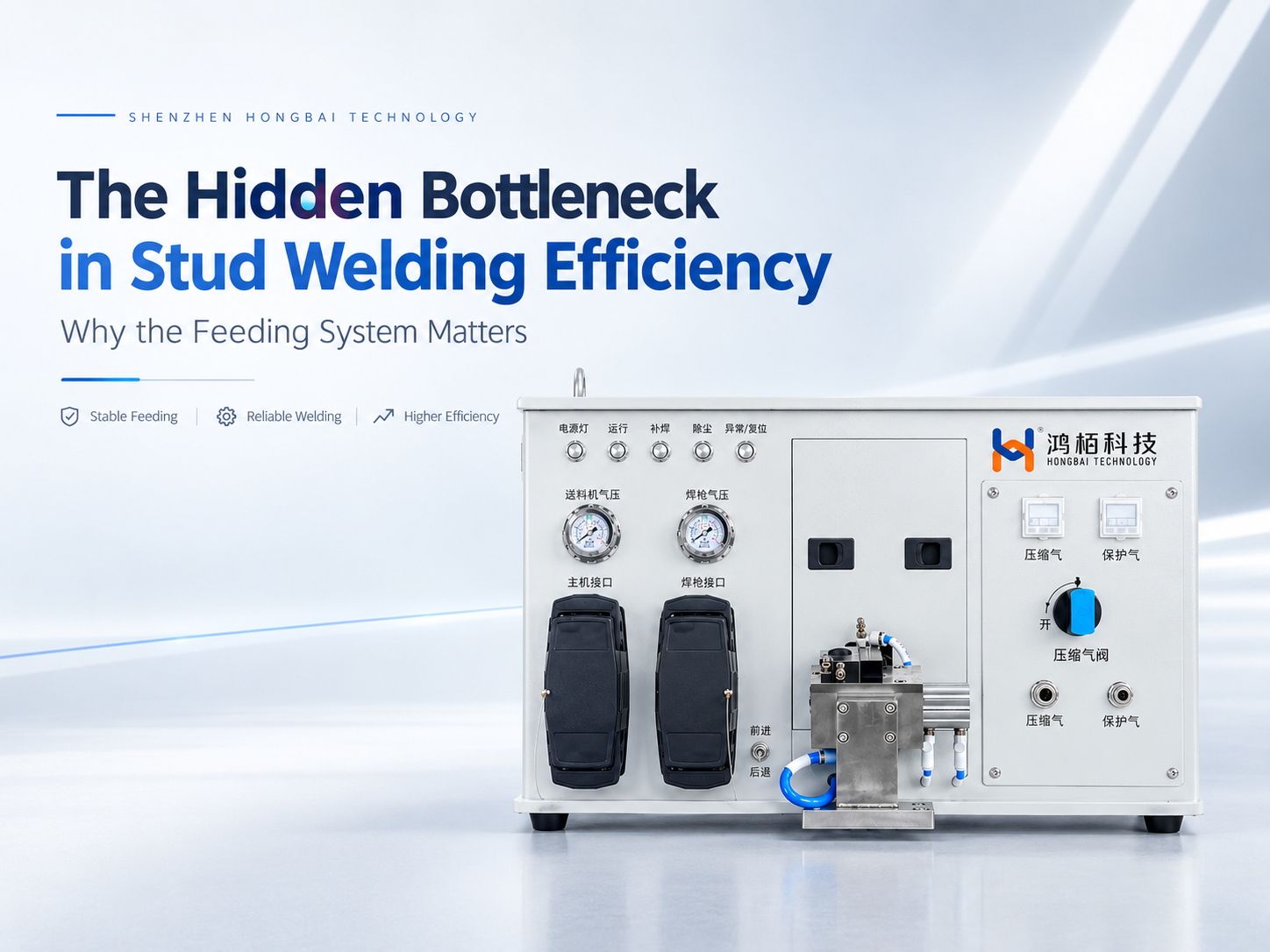
In automated stud welding, manufacturers naturally focus on the welding power source, weld gun, and robot. Welding current, weld time, positioning accuracy, and robot speed are all critical parameters. Yet when a system moves into continuous production, another factor often has a much greater impact on the actual production cycle than expected: how reliably the next stud is prepared for welding. A complete automated stud welding cycle involves much more than the welding operation itself. The stud must be separated, conveyed, positioned, loaded into the weld gun, and finally welded. If the feeding process is delayed or interrupted, the welding system and robot may have to wait, regardless of how fast the welding process itself can run. This is why the feeding system should not be treated simply as an accessory to a stud welding machine. In a high-volume production environment, it is part of the process that determines whether the entire welding cycle can continue smoothly. The goal of an automatic stud feeding system is not simply to feed a stud. It is to make sure the right stud is ready, in the right position, at the right time. 01 | When Welding Is Fast, Why Can Production Throughput Still Fall Short? When evaluating an automated stud welding system, welding time is usually one of the first parameters engineers consider. However, high performance at the welding stage does not automatically translate into high production throughput. The reason is that the actual production cycle includes several operations before the weld is made: Stud Separation → Feeding → Stud Positioning → Gun Loading → Robot Positioning → Welding Once one stud has been welded, the robot is ready to move to the next weld location. At the same time, the next stud needs to be prepared. If the robot reaches the…
2026-09-18
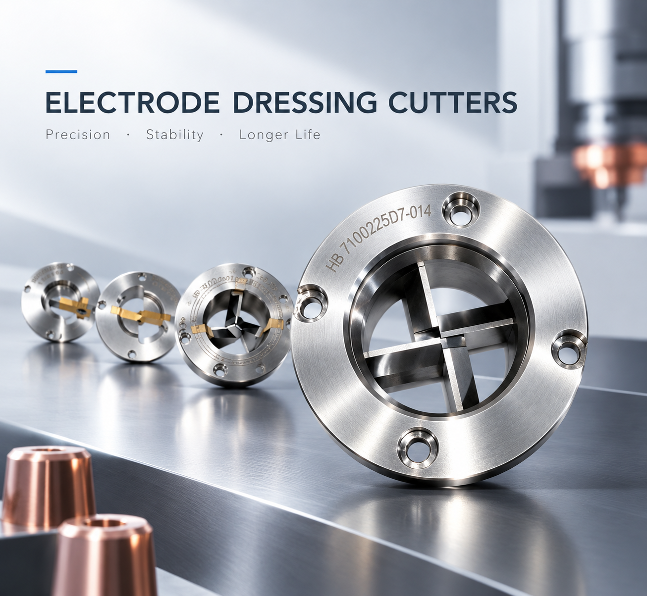
In Body-in-White (BIW) production, electrode cap dressing may seem like a relatively small operation. In practice, however, it has a direct connection with electrode cap life, weld consistency, production cycle time, and maintenance cost. Many problems on the shop floor do not start with a failure of the electrode dresser itself. They often develop gradually from the cutter: an unsuitable cutter selection, a mismatch between the cutter and dressing parameters, or continued use after the cutting edge has worn. The result may eventually appear as an abnormal electrode face, inconsistent dressing, or changes in weld quality. From our experience with electrode cap dressing applications, we believe that an electrode dressing cutter should not be selected based only on purchase price or theoretical tool life. The cutter, electrode cap, dressing machine, and process parameters need to work as one matched system. This is one of the key factors we consider when developing electrode cap dressing solutions. 1. Why Does an Electrode Dressing Cutter Affect Weld Quality? After continuous welding, the electrode cap gradually develops wear, deformation, and material buildup on its working face. If the electrode cap is not dressed at the appropriate interval, its geometry changes. This can affect the contact area and current density during resistance spot welding. The purpose of electrode cap dressing is not simply to “remove a layer” from the cap. The objective is to restore a stable: Electrode face diameter Face geometry Concentricity Surface condition Contact geometry The dressing cutter is the component that directly creates this geometry. When the cutter condition changes, the dressing result changes with it. For example, as a cutting edge becomes dull, the actual cutting condition may change even when spindle speed, dressing pressure, and dressing time remain unchanged. On the production line, this may appear as: Changes in electrode…
2026-09-15
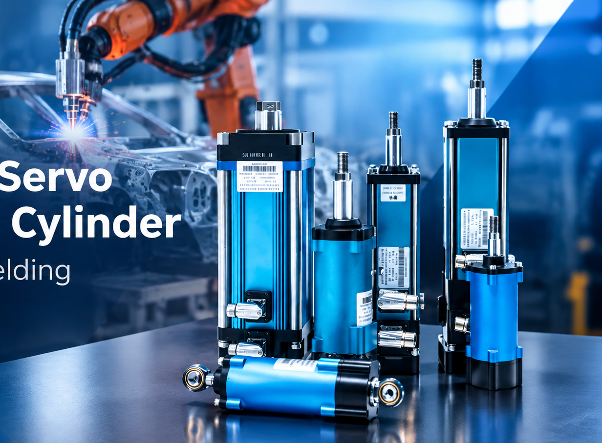
In robotic spot welding, welding current often gets most of the attention. But current alone does not determine whether a weld will be stable. Welding force, electrode movement, response speed and force repeatability also directly influence the welding process. This becomes even more important when one welding gun needs to handle different sheet thicknesses or when aluminum is introduced into automotive body structures. This is where the actuator inside the welding gun matters. A hollow servo electric cylinder combines servo actuation, precision screw transmission and position/force control into a compact linear unit. For robotic spot welding, its role goes beyond simply opening and closing the electrodes. It provides the mechanical and control foundation for accurate welding-force management and adaptive coordination between welding force and welding current. 1. What Is a Hollow Servo Electric Cylinder? 1. 什么是空心伺服电动气缸? A hollow servo electric cylinder is a linear actuator designed to convert servo motor rotation into controlled linear motion. Unlike a conventional actuator consisting of a servo motor, reduction mechanism and separate screw transmission, a linear integrated electric cylinder can place the motor and screw mechanism on the same axis. This shortens the transmission path and creates a more compact mechanical structure. For a robotic spot welding gun, this design has several practical benefits. The actuator needs to operate within a limited installation envelope while repeatedly generating high welding force. At the same time, the gun must move quickly enough to meet the cycle time of an automated production line. A shorter mechanical transmission path can help reduce unnecessary transmission components and provide a more direct connection between servo motion and electrode movement. This is one reason why a hollow servo electric cylinder for spot welding is particularly suitable for applications where compact installation, mechanical stiffness and dynamic response are important. 2. Why Does…
2026-09-08
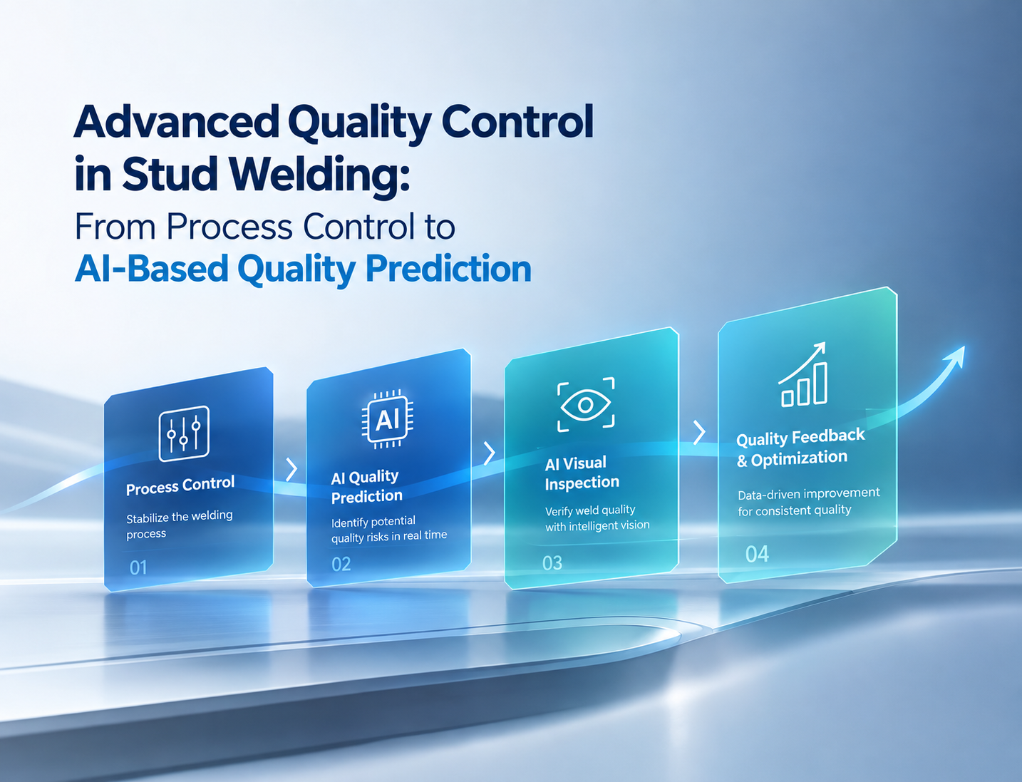
In stud welding production, the real challenge is often not whether a stud can be welded successfully, but whether it can be welded consistently and reliably over and over again. For a single stud, achieving a successful weld may not be particularly difficult. However, once stud welding is introduced into high-volume production environments such as automotive body-in-white, construction machinery, rail transportation, and sheet-metal manufacturing for home appliances, a single system may be required to perform thousands or even tens of thousands of welds continuously. At that point, weld quality is no longer determined simply by preset parameters such as weld current and weld time. Line voltage can fluctuate. The surface condition of the workpiece may vary due to oil contamination, oxidation, or coating differences. Pneumatic supply pressure may change. Equipment temperature may rise during extended operation. Different batches of studs may also vary in material properties and dimensional tolerances. Although these changes may appear minor, they can affect the arc condition, melting behavior, and final weld result within a welding cycle that takes place in milliseconds. For true high-volume manufacturing, therefore, the question is no longer simply: “Can this stud be welded successfully?” The more important question is: “When production conditions continuously change, how can the first stud and the last stud maintain as consistent a welding condition as possible?” This is exactly the challenge addressed by AQC2, Hongbai’s 2nd-Generation Active Quality Control technology, within the HEAS intelligent stud welding system. 1. From Parameter Execution to Active Control: A Changing Approach to Stud Weld Quality Traditional stud welding typically follows a straightforward sequence: Set Parameters → Perform Welding → Inspect After Welding Engineers set parameters such as weld current, weld time, and lift distance according to the workpiece material, stud specifications, and process requirements. The equipment then performs the weld…
2026-09-05
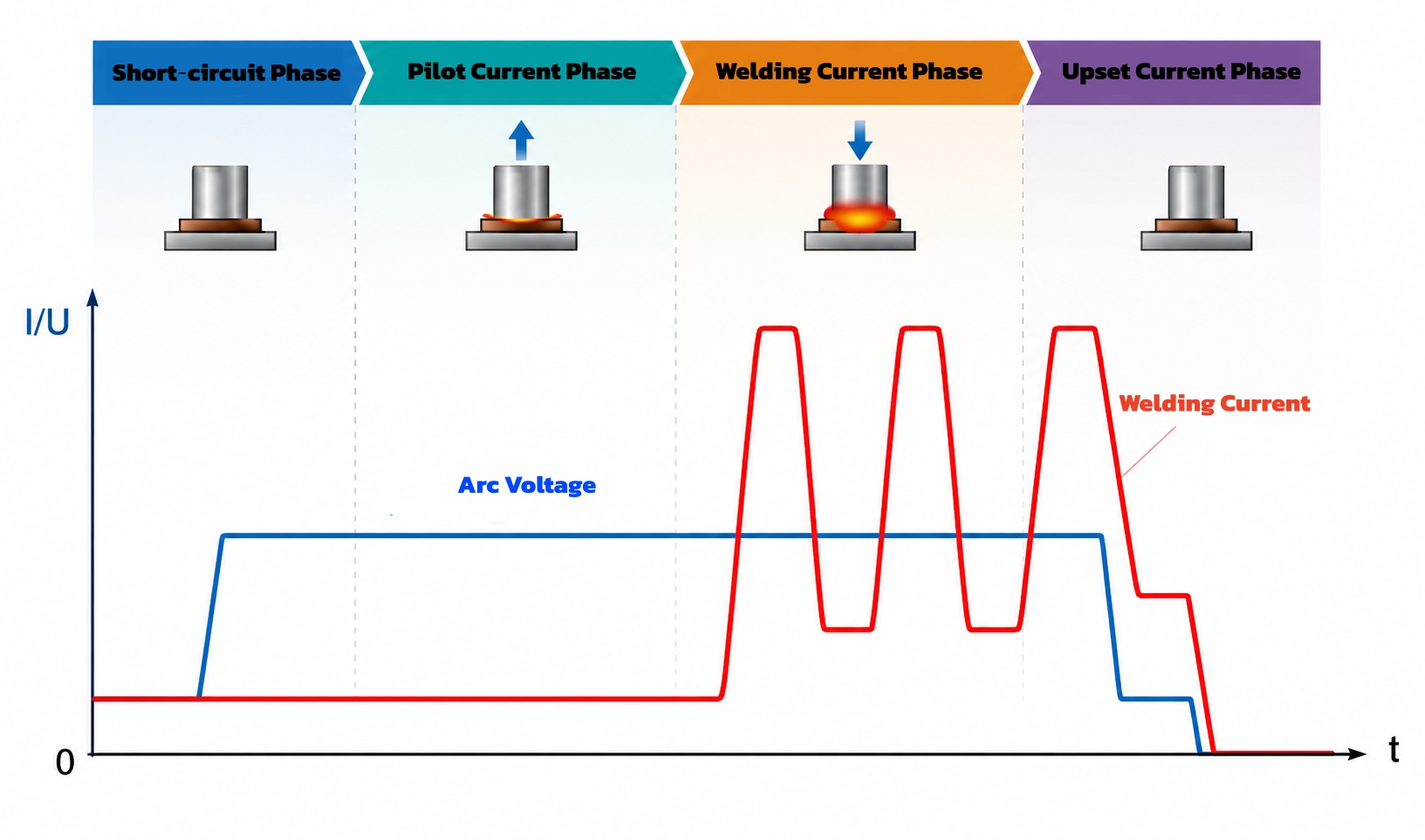
Why Monitor Penetration in Stud Welding? In stud welding, the result is not simply about whether the stud is attached to the workpiece. When the stud tip and workpiece surface are melted, sufficient fusion must be achieved to form a reliable joint. Insufficient fusion can affect joint strength, while excessive heat input may cause localized overheating or even burn-through when welding thin sheet metal. In conventional production, engineers typically control the process through parameters such as welding current, welding time, and lift height, followed by visual inspection and sampling-based destructive testing. But these methods do not always answer a more direct question: What actually happened to this individual stud during the weld? This is where the penetration monitoring function of the PIDS Series Stud Welding System comes into play. The system monitors the change in stud position before and after welding, calculates the corresponding penetration value, and provides the result on the operator interface after the weld is completed. Penetration therefore becomes a measurable process variable rather than something that can only be evaluated indirectly through post-weld inspection. 1. How Does PIDS Penetration Monitoring Work? 1.1 The Principle Is Measurement, Not Visual Inspection PIDS penetration monitoring does not rely on a camera to directly observe the molten pool after welding. Instead, it is based on the change in stud position before and after the welding cycle. Before welding begins, the system establishes the initial stud position as a reference. Once the arc is initiated, the stud tip and workpiece surface melt to form a molten pool. The stud then moves into the molten pool and the weld is completed. After welding, the system records the final stud position. The change between the initial and final positions is then used to calculate the corresponding penetration value. The process can be simplified…
2026-09-01
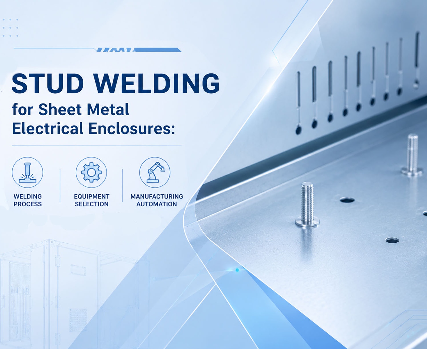
1. Stud Welding in Sheet Metal Electrical Enclosure Manufacturing Stud welding is widely used for fastening applications in electrical enclosures, control cabinets, switchgear cabinets, distribution boxes, and other sheet metal structures. Compared with conventional nut welding, drilling and tapping, or mechanical fastening, stud welding allows a threaded stud or fastening element to be permanently attached directly to the sheet metal surface, reducing additional machining and assembly operations. Typical applications include grounding studs, mounting studs for circuit breakers and terminal blocks, busbar supports, cable management components, door hardware, and other internal cabinet components. In practical production, the selection of a sheet metal stud welding process depends mainly on sheet thickness, stud diameter, base material, required joint strength, surface condition, and the appearance requirements of the opposite side of the workpiece. For thin sheet metal electrical enclosures, minimizing distortion, discoloration, and visible marks on the reverse side can be particularly important. For structural components and grounding connections, weld strength and process consistency may take priority. Therefore, selecting stud welding equipment for electrical enclosures requires more than simply checking the welding current or stud diameter. The welding power source, stud welding gun, stud feeder, workholding system, and level of automation all need to be considered as part of the same process. 2. Capacitor Discharge and Drawn Arc Stud Welding 2.1 Capacitor Discharge Stud Welding Capacitor discharge (CD) stud welding stores electrical energy in capacitors and releases it over an extremely short welding cycle. Typical welding time is approximately 0.001–0.003 seconds, with peak current reaching approximately 5,000–10,000 A. Because the welding cycle is extremely short, heat input is concentrated around the weld area. This makes capacitor discharge stud welding particularly suitable for thin sheet metal and applications where backside appearance is important. Hongbai’s PFC Series capacitor discharge stud welding machines support stud diameters from…
2026-08-26
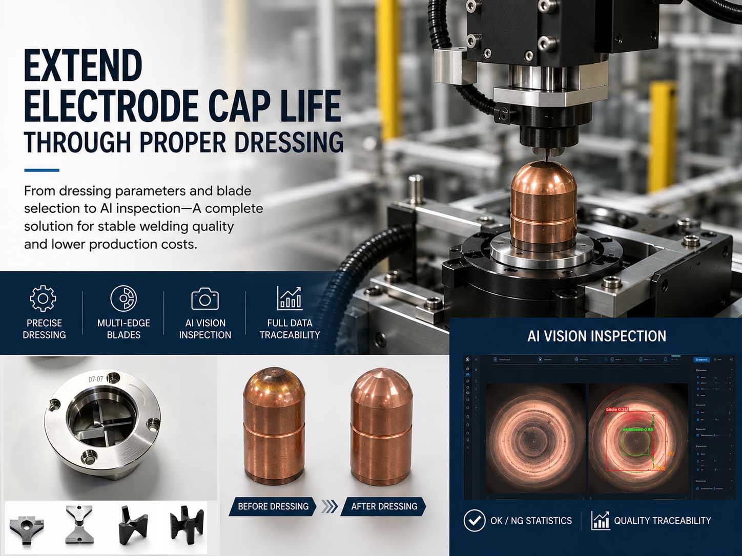
An electrode cap is a critical consumable component in resistance spot welding. It directly participates in the welding process and plays an important role in maintaining stable electrical and mechanical conditions at the weld interface. In automotive manufacturing, Body-in-White (BIW) production and other high-volume automated spot welding applications, the condition of the electrode cap can directly affect weld quality, process stability and production efficiency. As the number of welds increases, the working face of the electrode cap gradually becomes worn, deformed or contaminated. Copper pickup, surface marks and other irregularities may also develop during continuous welding. Electrode cap dressing is therefore used to remove the damaged surface layer and restore the required geometry and working condition of the electrode cap. However, electrode cap dressing is not simply a matter of removing as much material as possible.Insufficient dressing may leave damaged areas on the working face, while excessive dressing unnecessarily removes electrode material and reduces the number of effective dressing cycles available from a single electrode cap. Therefore, controlling the dressing amount, selecting the right dressing cutter, performing routine maintenance and using intelligent inspection to identify abnormalities are all important for extending electrode cap life. In practical production applications, electrode cap dressing performance can be systematically improved through four key areas. 1. Control the Dressing Amount to Avoid Excessive Material Removal The primary objective of electrode cap dressing is to remove damaged material and restore the required working face—not to remove more material than necessary. If the dressing amount is insufficient, defects generated during welding may remain on the electrode face, including black marks, raised areas, localized wear and uneven surfaces. These conditions can alter current density and electrode force distribution, potentially affecting weld consistency. On the other hand, excessive dressing removes a larger amount of otherwise usable electrode material. This…