
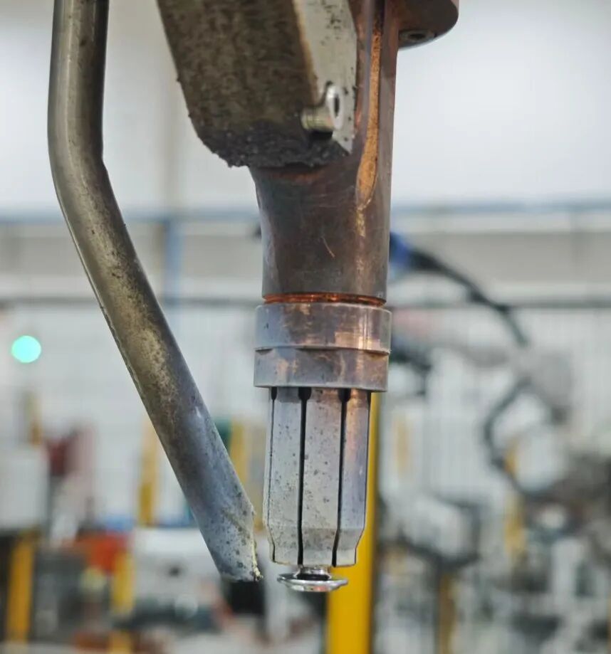
The support leg (or standoff leg) is a critical component on a stud welding gun, particularly on automatic welding guns. Below is a detailed explanation of its function and the best method for adjustment:
I. Functions of the Support Leg
The support leg (also referred to in some documentation as the foot assembly or front support leg) has the following primary functions:
1. Positioning the Stud Plunge/Protrusion: The support leg is used to determine the protruding length of the stud end relative to the front face of the welding gun (i.e., the stud plunge/protrusion length). This is a critical parameter affecting weld quality.
2. Ensuring Stud Alignment: The support leg works in conjunction with the chuck and the ferrule (or ceramic arc shield) to ensure the stud is centered in the welding gun, preventing welding defects caused by misalignment or off-center positioning.
3. Stabilizing the Welding Position: During the welding process, the support leg contacts the workpiece surface, ensuring a fixed relative position between the welding gun and the workpiece, thereby preventing gun movement or instability during welding.
4. Protecting the Contact Tip: The support leg is designed such that the end face of the contact tip is recessed approximately 2 mm below the end face of the support leg, effectively protecting the contact tip from damage caused by contact with the workpiece.
II. Best Method for Adjusting the Support Leg
Step 1: Verify Basic Conditions
• The gun piston rod is naturally extended forward under compressed air pressure.
• A stud is loaded into the contact tip.
• The stud is in its final welding position within the contact tip.
Step 2: Adjust the Support Leg Position
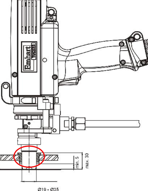
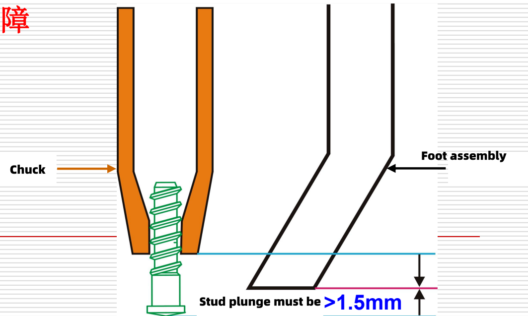
Core Principle: The support leg must be positioned between the chuck and the stud. It must not be located behind the chuck, to prevent the chuck from accidentally welding when no stud is loaded.
Detailed Adjustment Steps:
|
|
|
|
|---|---|---|
|
|
|
|
|
|
|
|
|
|
|
|
|
|
|
|
|
|
|
|
Step 3: Verify Plunge Length
Optimal Adjustment Range: 2 mm < Stud Plunge < 3 mm
◦ Too Short (< 2 mm): May result in a “Insufficient Plunge” error.
◦ Too Long (> 3 mm): May cause a “Lift Error” fault.
• Supplementary Requirement: The stud plunge must be greater than 1.5 mm.
Step 4: Periodic Inspection
|
|
|
|---|---|
| Daily |
|
| Weekly |
|
| After each loosening |
|
III. Key Points for Optimal Results
1. Use an Adjustment Gauge: It is recommended to use an adjustment gauge that corresponds to the specific stud size for precise adjustment, rather than relying solely on visual inspection.
2. Prioritize Concentricity: Misalignment between the support leg and the stud will hinder the stud’s plunge motion into the molten weld pool during welding, resulting in weld defects.
3. Post-Weld Inspection: Before each batch of production welding, perform test welds and fine-tune the support leg position based on the actual weld results.
4. Reference Values for Different Gun Types:
|
|
|
|
|---|---|---|
|
|
|
|
|
|
|
|
|
|
|
|
The optimal adjustment results for the support leg are achieved by:
• Ensuring a stud plunge of 2–3 mm.
• Maintaining concentricity with the stud.
• Positioning the support leg between the chuck and the stud.
Under these prerequisites, precise adjustment is performed using a professional gauge, followed by fine-tuning based on actual weld quality after test welding. Regular cleaning of weld spatter and inspection for wear are key to maintaining long-term stability of the adjustment results.
👉Contact us for technical consultation