
2026-09-30
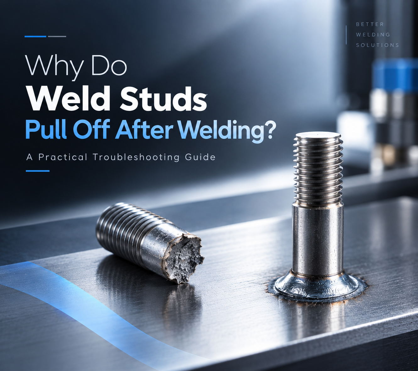
The weld cycle is complete. The stud looks properly welded, and the welding system shows no obvious alarm. Then, during assembly or a pull test, the weld stud breaks away from the workpiece. For engineers responsible for welding quality, this is a familiar but frustrating situation. The first reaction is often to increase the welding current or extend the weld time. Sometimes that changes the result. But if the actual cause lies in stud positioning, grounding, surface condition, feeding stability, or process repeatability, changing the welding parameters alone may only move the problem from one place to another. A more reliable approach is to look at the complete welding process and determine where the weld started to lose stability. 02|Start With the Failed Weld Before changing any welding parameters, start with the failed weld itself. The fracture surface can provide useful evidence about how the weld was formed. Little visible fusion may point toward insufficient heat input or unstable arc conditions. Uneven fusion around the stud may indicate problems with gun alignment, stud positioning, grounding, or surface condition. It is also important to distinguish between a stud that never achieved sufficient fusion and one that formed a weld but later failed under mechanical loading. These two situations may look similar from the outside, but they require different troubleshooting approaches. Cross-section analysis can reveal the difference between proper fusion, partial fusion, and lack of fusion in stud welding. The first question should therefore be: What does the failed weld tell us about how the weld was formed? Observed Condition Possible Direction of Investigation Little or no visible fusion Welding current, weld time, lift height, arc stability Uneven fusion around the stud Gun alignment, stud positioning, grounding Excessive spatter Heat input, arc conditions, parameter combination Weld looks acceptable but stud pulls off…
2026-09-21
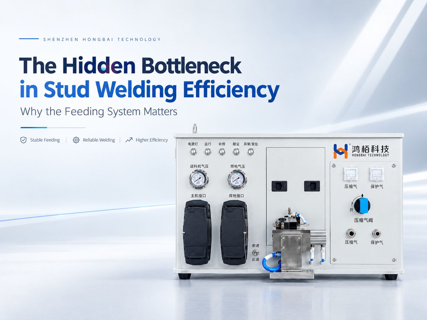
In automated stud welding, manufacturers naturally focus on the welding power source, weld gun, and robot. Welding current, weld time, positioning accuracy, and robot speed are all critical parameters. Yet when a system moves into continuous production, another factor often has a much greater impact on the actual production cycle than expected: how reliably the next stud is prepared for welding. A complete automated stud welding cycle involves much more than the welding operation itself. The stud must be separated, conveyed, positioned, loaded into the weld gun, and finally welded. If the feeding process is delayed or interrupted, the welding system and robot may have to wait, regardless of how fast the welding process itself can run. This is why the feeding system should not be treated simply as an accessory to a stud welding machine. In a high-volume production environment, it is part of the process that determines whether the entire welding cycle can continue smoothly. The goal of an automatic stud feeding system is not simply to feed a stud. It is to make sure the right stud is ready, in the right position, at the right time. 01 | When Welding Is Fast, Why Can Production Throughput Still Fall Short? When evaluating an automated stud welding system, welding time is usually one of the first parameters engineers consider. However, high performance at the welding stage does not automatically translate into high production throughput. The reason is that the actual production cycle includes several operations before the weld is made: Stud Separation → Feeding → Stud Positioning → Gun Loading → Robot Positioning → Welding Once one stud has been welded, the robot is ready to move to the next weld location. At the same time, the next stud needs to be prepared. If the robot reaches the…
2026-09-15
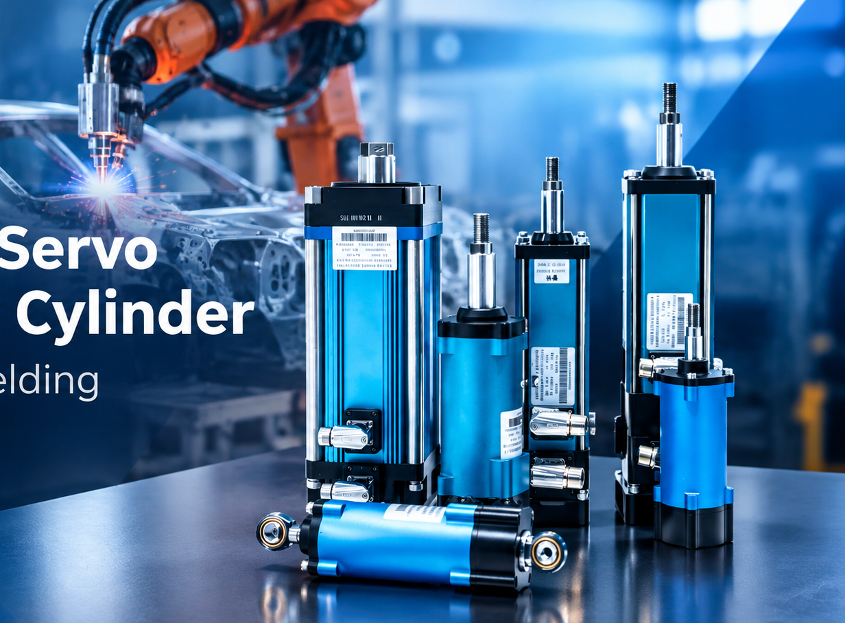
In robotic spot welding, welding current often gets most of the attention. But current alone does not determine whether a weld will be stable. Welding force, electrode movement, response speed and force repeatability also directly influence the welding process. This becomes even more important when one welding gun needs to handle different sheet thicknesses or when aluminum is introduced into automotive body structures. This is where the actuator inside the welding gun matters. A hollow servo electric cylinder combines servo actuation, precision screw transmission and position/force control into a compact linear unit. For robotic spot welding, its role goes beyond simply opening and closing the electrodes. It provides the mechanical and control foundation for accurate welding-force management and adaptive coordination between welding force and welding current. 1. What Is a Hollow Servo Electric Cylinder? 1. 什么是空心伺服电动气缸? A hollow servo electric cylinder is a linear actuator designed to convert servo motor rotation into controlled linear motion. Unlike a conventional actuator consisting of a servo motor, reduction mechanism and separate screw transmission, a linear integrated electric cylinder can place the motor and screw mechanism on the same axis. This shortens the transmission path and creates a more compact mechanical structure. For a robotic spot welding gun, this design has several practical benefits. The actuator needs to operate within a limited installation envelope while repeatedly generating high welding force. At the same time, the gun must move quickly enough to meet the cycle time of an automated production line. A shorter mechanical transmission path can help reduce unnecessary transmission components and provide a more direct connection between servo motion and electrode movement. This is one reason why a hollow servo electric cylinder for spot welding is particularly suitable for applications where compact installation, mechanical stiffness and dynamic response are important. 2. Why Does…
2026-08-26
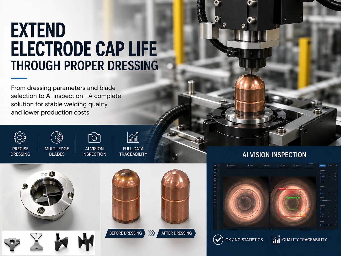
An electrode cap is a critical consumable component in resistance spot welding. It directly participates in the welding process and plays an important role in maintaining stable electrical and mechanical conditions at the weld interface. In automotive manufacturing, Body-in-White (BIW) production and other high-volume automated spot welding applications, the condition of the electrode cap can directly affect weld quality, process stability and production efficiency. As the number of welds increases, the working face of the electrode cap gradually becomes worn, deformed or contaminated. Copper pickup, surface marks and other irregularities may also develop during continuous welding. Electrode cap dressing is therefore used to remove the damaged surface layer and restore the required geometry and working condition of the electrode cap. However, electrode cap dressing is not simply a matter of removing as much material as possible.Insufficient dressing may leave damaged areas on the working face, while excessive dressing unnecessarily removes electrode material and reduces the number of effective dressing cycles available from a single electrode cap. Therefore, controlling the dressing amount, selecting the right dressing cutter, performing routine maintenance and using intelligent inspection to identify abnormalities are all important for extending electrode cap life. In practical production applications, electrode cap dressing performance can be systematically improved through four key areas. 1. Control the Dressing Amount to Avoid Excessive Material Removal The primary objective of electrode cap dressing is to remove damaged material and restore the required working face—not to remove more material than necessary. If the dressing amount is insufficient, defects generated during welding may remain on the electrode face, including black marks, raised areas, localized wear and uneven surfaces. These conditions can alter current density and electrode force distribution, potentially affecting weld consistency. On the other hand, excessive dressing removes a larger amount of otherwise usable electrode material. This…
2026-08-19
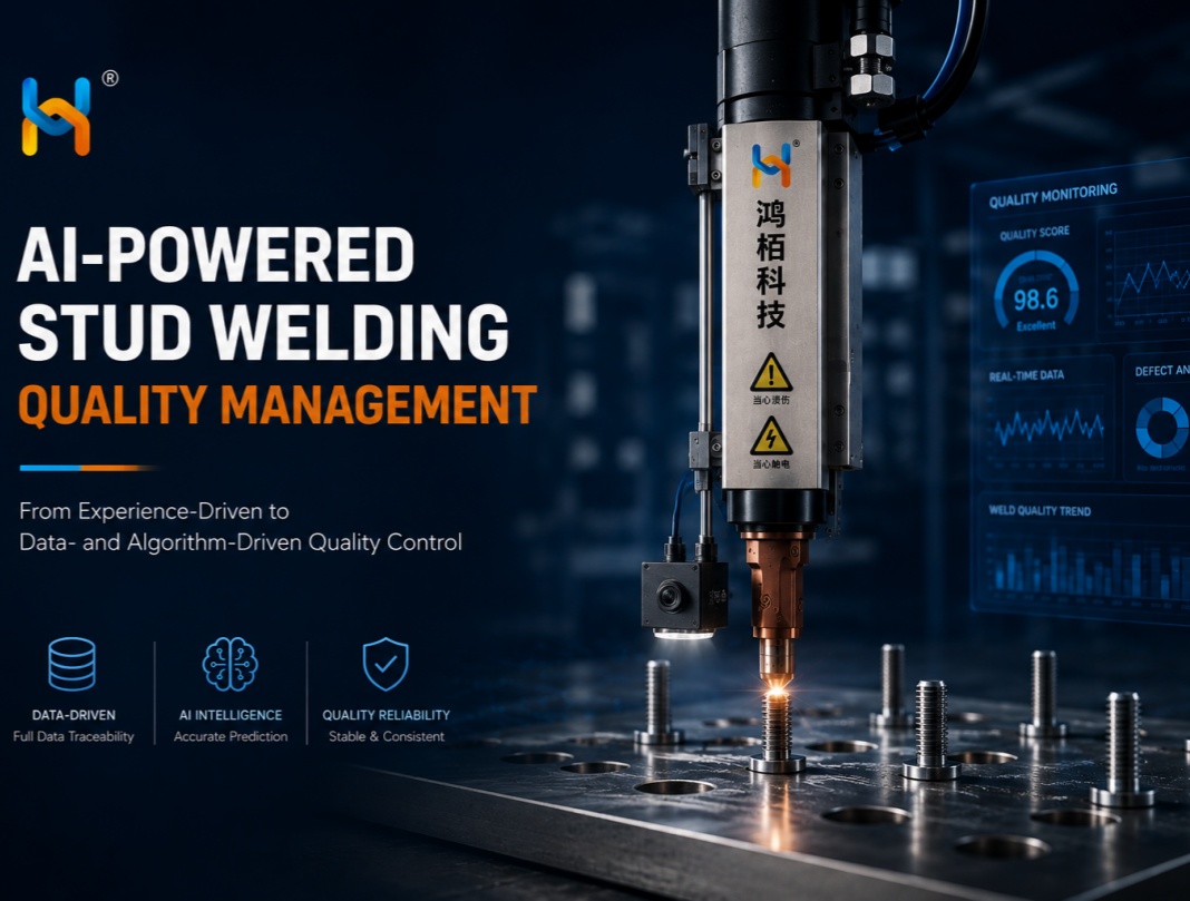
In July 2026, at the AMTS Shanghai International Automotive Manufacturing Technology & Material Show, Hongbai Technology made the global debut of its fully self-developed AI foundation-model-powered stud welding quality inspection system. It is also the world’s first quality management system integrating an AI foundation model specifically for stud welding applications. As AI foundation models rapidly transform industries worldwide, Hongbai Technology is bringing this transformation to the welding industry. After six generations of welding technology evolution, the company has consistently focused on the integration of data, algorithms, and real-world industrial scenarios, while addressing four fundamental challenges in industrial AI. Through the dual revolution of “Welding + AI,” Hongbai Technology is pioneering a new paradigm for stud welding quality management—moving from experience-driven quality control to data- and algorithm-driven intelligence. 1. Industry Challenges: Four Limitations of Traditional Quality Inspection 1.1 Fragmented and Heterogeneous Data In high-volume stud welding production, traditional quality management faces a series of systemic challenges. Fragmented and heterogeneous data: Quality records are often scattered across paper documents, PowerPoint files, Excel spreadsheets, welding equipment, and other systems, making data integration time-consuming and inefficient. 1.2 Slow Problem Detection and Response Quality issues may take up to four hours to be detected under periodic inspection. Once identified, the escalation and feedback process may require another 1–2 hours, while problem resolution can take up to 3.5 hours. In addition, compiling daily quality inspection reports can consume approximately 2.25 hours of labor every day. For high-volume automotive production, such delays increase the risk of quality issues escaping downstream and can lead to additional rework and production costs. 1.3 Manufacturing Knowledge Is Difficult to Capture and Reuse Root cause identification and corrective action often depend heavily on the experience of individual engineers and technicians. When critical welding knowledge remains primarily within individual experts, it becomes difficult…
2026-08-11
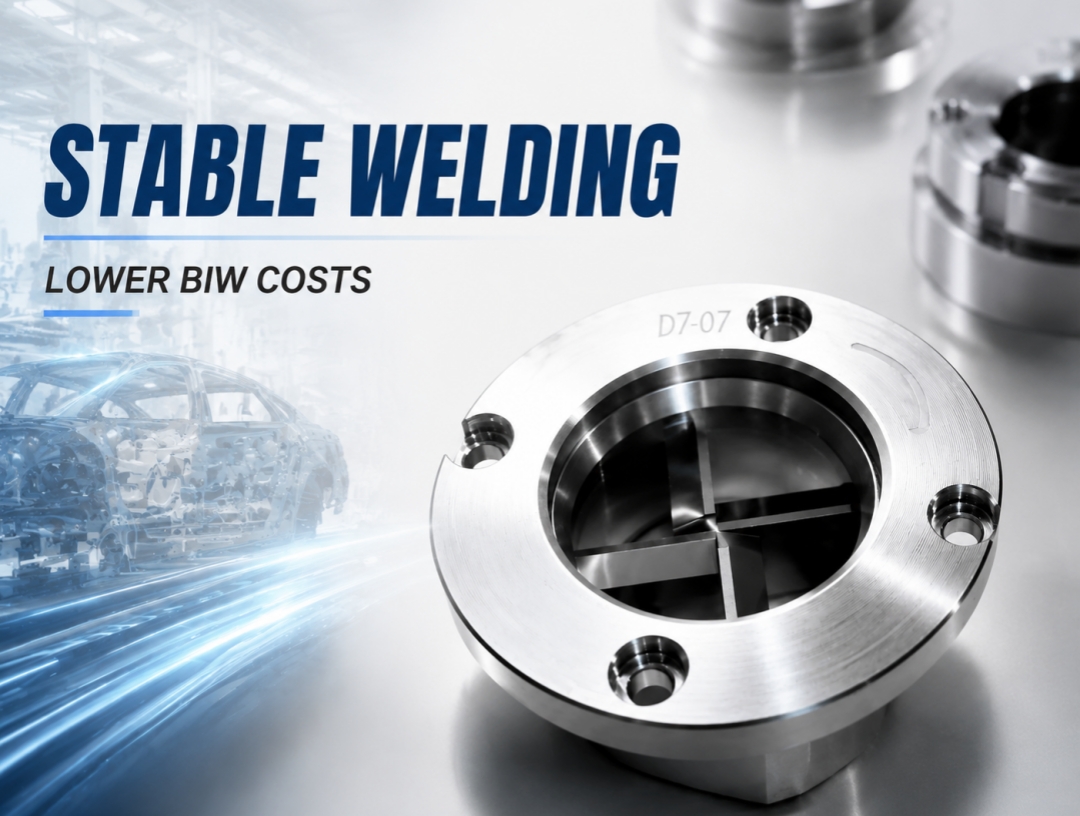
In the demanding environment of automotive Body-in-White (BIW) welding, electrode cap dressing blades may appear small, but they play a critical role in determining weld spot quality, electrode cap service life, and overall production cost. Behind a seemingly simple blade lies a complete chain of engineering expertise, including material science, precision manufacturing, and strict quality management. With decades of experience in welding equipment development, Shenzhen Hongbai Technology Co., Ltd. has successfully transformed its independently developed electrode cap dressing blades from ordinary consumable components into precision-engineered products integrating advanced structural design, high-accuracy manufacturing processes, and international certification standards. 1. Design Philosophy: A Fundamental Shift from “Cutting” to “Dressing” Traditional electrode cap dressing is essentially a cutting process, where sharp cutting edges forcibly remove the copper-aluminum alloy layer accumulated on the electrode cap surface. Although this method is straightforward, it has two major limitations: High material removal rate (approximately 0.08 mm per dressing cycle) Short blade service life (only around 8,000–12,000 dressing cycles for single-edge blades) Hongbai’s dressing blade design achieves a breakthrough by redefining the fundamental dressing principle. 1.1 Multi-Edge Structure: From Single Cutting to Multi-Stage Dressing The core innovation of Hongbai dressing blades lies in the multi-edge structure. Currently, Hongbai provides four blade configurations. Taking the four-edge blade as an example, its four cutting edges are arranged at 90-degree intervals. During the dressing process, multiple edges work simultaneously, distributing cutting forces across several contact points. This reduces the material removal amount per dressing cycle to only 0.01–0.035 mm, bringing the process closer to precision dressing rather than conventional cutting. The direct benefits include: Reduced electrode cap material consumption Extended electrode cap service life Increased welding capacity from approximately 3,000 weld spots to 6,000 weld spots per pair of electrode caps 1.2 Four-Edge Right-Angle Design: 90° Geometry and 0.01 mm Dressing…