
Although defects such as weld nugget deviation and cold welds/incomplete fusion cannot be completely eliminated, their occurrence can be reduced to an extremely low level through systematic process control, real-time quality monitoring, and regular equipment maintenance.
The following solutions focus on two critical defect areas — weld nugget deviation and cold welding/incomplete fusion — combining proven process optimization methods with advanced intelligent welding technologies.
1. Precise Control of Weld Nugget Deviation
Weld nugget deviation is mainly caused by arc blow (magnetic arc deflection) and uneven heat dissipation conditions.
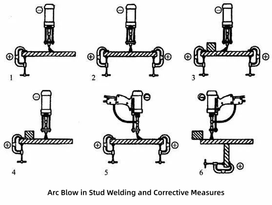
1.1 Eliminating Arc Blow — Prevention at the Source
Symmetrical grounding (core measure)
The ground connections should be positioned symmetrically on both sides of the welding location.
This prevents uneven electromagnetic fields from deflecting the arc and is the most effective method for eliminating arc blow.
Remove or ground nearby metal masses
If large metal components, reinforcement plates, or conductive structures are located close to one side of the weld area, they should be removed or properly grounded to avoid magnetic field interference.
Rotate the welding torch
For manual 螺柱焊接, if arc deflection occurs toward one direction, rotating the torch handle by 90° can change the magnetic field distribution and improve arc stability.
Control lift height
Excessive lift height or missing ceramic ferrules can increase arc instability.
Recommended lift height:
- General range: 1.0–1.6 mm
- Always use ceramic ferrules whenever possible to stabilize the arc.
Figure: Symmetrical Grounding Configuration for Arc Blow Prevention
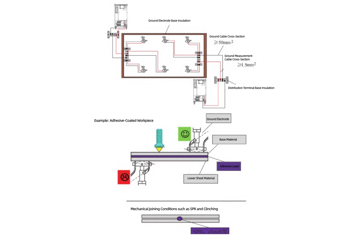
Proper grounding layout plays a critical role in stabilizing the welding arc. Symmetrical grounding reduces magnetic field imbalance and prevents arc deflection, helping maintain consistent weld nugget positioning.
1.2 Optimizing Heat Distribution for Different Materials and Thicknesses
Apply high-energy welding parameters
Using a high current and short welding time (strong welding schedule) increases current density and reduces the influence of heat conduction differences, helping maintain a centered weld nugget.
Optimize chuck/electrode configuration
- Use a smaller diameter chuck on the thinner or higher thermal conductivity side to increase current density.
- Use a larger diameter electrode on the thicker side.
Use thermal balancing shims
Installing a low thermal conductivity metal shim (approximately 0.2–0.3 mm) under the thinner material side can reduce heat loss and balance weld nugget growth.
2. Advanced Solutions for Cold Welds / Incomplete Fusion / Small Weld Nuggets
The primary cause of cold welding is insufficient heat input or poor contact conditions.
2.1 Welding Parameter Optimization (Fundamental Approach)
Current and time matching
According to the heat input principle:
Q = I²Rt
一个 high current + short duration welding schedule is recommended because it improves penetration and reduces excessive heat affected zone (HAZ).
Pilot current / pilot time
For galvanized steel or coated surfaces:
Increase pilot time (for example, from 50 ms to 60 ms)
Adjust pilot current accordingly
This helps remove surface contaminants and reduces defects caused by zinc vapor, contamination, or unstable arc initiation.
Lift height adjustment
Recommended values:
| Material | Recommended Lift Height |
|---|---|
| Aluminum studs | 1.0–1.6 mm |
| Steel studs | 1.2–3.0 mm |
Fine adjustment should be made according to material thickness and welding conditions.
Forging current / forging time
Proper setting of forging parameters helps maintain molten pool stability and improve nugget formation.
Typical range:
Forging current: 150–300 A
Forging time: 5–12 ms
2.2 Real-Time Welding Energy Monitoring and Compensation
(Advanced Intelligent Control)
Enable energy compensation function
The PIDS system monitors the deviation between actual arc voltage and the target arc voltage, automatically compensating welding current when necessary.
This reduces the risk of cold welds caused by:
- Power supply fluctuation
- Contact resistance variation
- Surface condition changes
Set energy/power deviation limits
For example, the SAW series controller can monitor welding energy output through:
Power lower deviation limit (80–90%)
If actual welding energy falls below the defined limit:
- System generates an alarm
- Production can be stopped automatically
- Defective welds are prevented from entering downstream processes
Apply AQC2 (2nd Generation Active Quality Control)
Systems such as SAW-3600R with AQC2 technology use:
- Servo-controlled arc length regulation
- Precise arc voltage control
- Real-time energy feedback compensation
This allows the welding process to withstand external disturbances, including:
- Power fluctuations
- Surface condition variations
- Contact resistance changes
Ensuring consistent weld quality for every stud.
2.3 Workpiece Surface and Assembly Condition Control
Strict surface cleaning
The welding area must be free from:
- Oil contamination
- Coatings
- Rust
- Oxides
Pre-cleaning or pilot current cleaning should be applied when necessary.
Minimize assembly gaps
Excessive gaps (>0.5 mm) can directly cause insufficient penetration or cold welds.
Recommended actions:
- Use proper fixtures
- Apply sufficient clamping force
- Control robot pressing force
Control stud stick-out length
Recommended:
- Stud end should extend 2–3 mm above the chuck or anti-spatter sleeve
- Support rod position must be correctly maintained between chuck and stud
2.4 Alignment and Vibration Control
Stud perpendicularity
Stud inclination should be controlled within:
±3°
Excessive tilt may cause:
- One-side incomplete fusion
- Uneven weld nugget formation
Vibration and spacing control
Recommended:
- Minimum distance between weld points: ≥10 mm
- Avoid concentrated welding areas that may cause uneven heat accumulation
When multiple welding processes are applied on the same workpiece:
- Welding sequences should be separated
- Electromagnetic interference should be minimized
2.5 Electrode / Chuck Maintenance
Chuck maintenance
Daily requirements:
- Remove welding spatter
- Check gripping force
- Maintain proper contact condition
If the chuck bore becomes enlarged due to wear, the probability of cold weld defects increases significantly.
Plunger / support rod maintenance
Wear may affect:
- Return stroke
- Lift height accuracy
- Weld nugget formation
Recommended:
- Regular inspection (weekly to monthly)
- Lubrication when movement becomes slow
- Replace sealing components if required
3. Defect-Tolerant Process Control for Low-Probability Failures
Even with optimized welding parameters, occasional defects may occur due to random process variations.
Recommended countermeasures:
3.1 Post-Weld Inspection and Repair Process
Bend test
Procedure:
- Bend the stud by 15° and inspect the weld root
- If partial incomplete fusion appears, do not exceed 45°
- Perform verification bending from the opposite direction
If large-area incomplete fusion occurs:
→ Perform rework welding.
Welding deviation handling
PIDS systems support:
- Weld point skip and marking
- Defective points are identified and repaired offline
- Automatic re-welding
- If the stud is missing, a new stud can be automatically fed and welded
SAW systems support:
- CO₂ repair welding
- Stud replacement and re-welding
3.2 Key Process Control Checklist
| Inspection Item | Requirement |
|---|---|
| First article inspection | Weld 3–5 studs and perform bend/torque testing |
| Material or model change | Perform trial welding before mass production |
| Feeding system | Ensure sufficient stud quantity |
| Air pressure | Maintain 5–7 kg/cm² |
| Stud feeding tube | Ensure no bending or blockage |
4. Summary: Effectiveness Ranking of Defect Control Methods
| Control Method | Effectiveness Level | Application & Benefits |
|---|---|---|
| Enable energy compensation + AQC2 Active Quality Control | ⭐⭐⭐⭐⭐ | Provides systematic resistance against power fluctuations, contact variation, and surface condition changes. Significantly reduces cold weld probability. |
| Optimize welding parameters (high current, short time, lift height, forging parameters) | ⭐⭐⭐⭐ | Fundamental method suitable for all welding applications. Requires process trials and optimization of current/time profiles. |
| Symmetrical grounding + arc blow prevention measures | ⭐⭐⭐⭐ | Most effective solution for controlling weld nugget deviation caused by magnetic arc deflection. |
| Strict surface preparation + stud perpendicularity control within ±3° | ⭐⭐⭐⭐ | Low-cost, high-return measures that eliminate major causes of welding defects. |
| Post-weld inspection + automatic rework system | ⭐⭐⭐ | Provides defect containment and prevents non-conforming products from reaching customers. |
Recommended Strategy
The most effective approach is to combine:
Energy compensation (such as AQC2 Active Quality Control)
+
Strong welding schedules (high current, short welding time)
+
Symmetrical grounding and proper surface preparation
+
Post-weld inspection and automated rework processes
This integrated approach enables systematic control of weld nugget deviation and cold weld defects, reducing defect rates to an extremely low level while achieving stable, repeatable stud welding quality.