


Hongbai Technology Technical Column | Professional Series
Introduction
In 螺柱焊接, a small change in current or welding time can make a noticeable difference to the final weld. Too little energy may result in incomplete fusion, while excessive heat can cause spatter, an irregular weld collar, or burn-through on thin sheet metal.
On Hongbai Technology’s SAW-3600 series stud welding system, parameters such as pilot current, welding current, and upset time are used to configure the welding cycle. Getting the best result is not simply a matter of increasing the current. The stud, base material, surface condition, lift height, and welding gun movement all need to be considered together.
This article looks at how these parameters work, the reference settings available on the equipment, and what to consider when adjusting them for different applications.
1. How the Stud Welding Cycle Works
In the servo-controlled welding process described here, the electrical output and the mechanical movement of the stud work together through four stages.
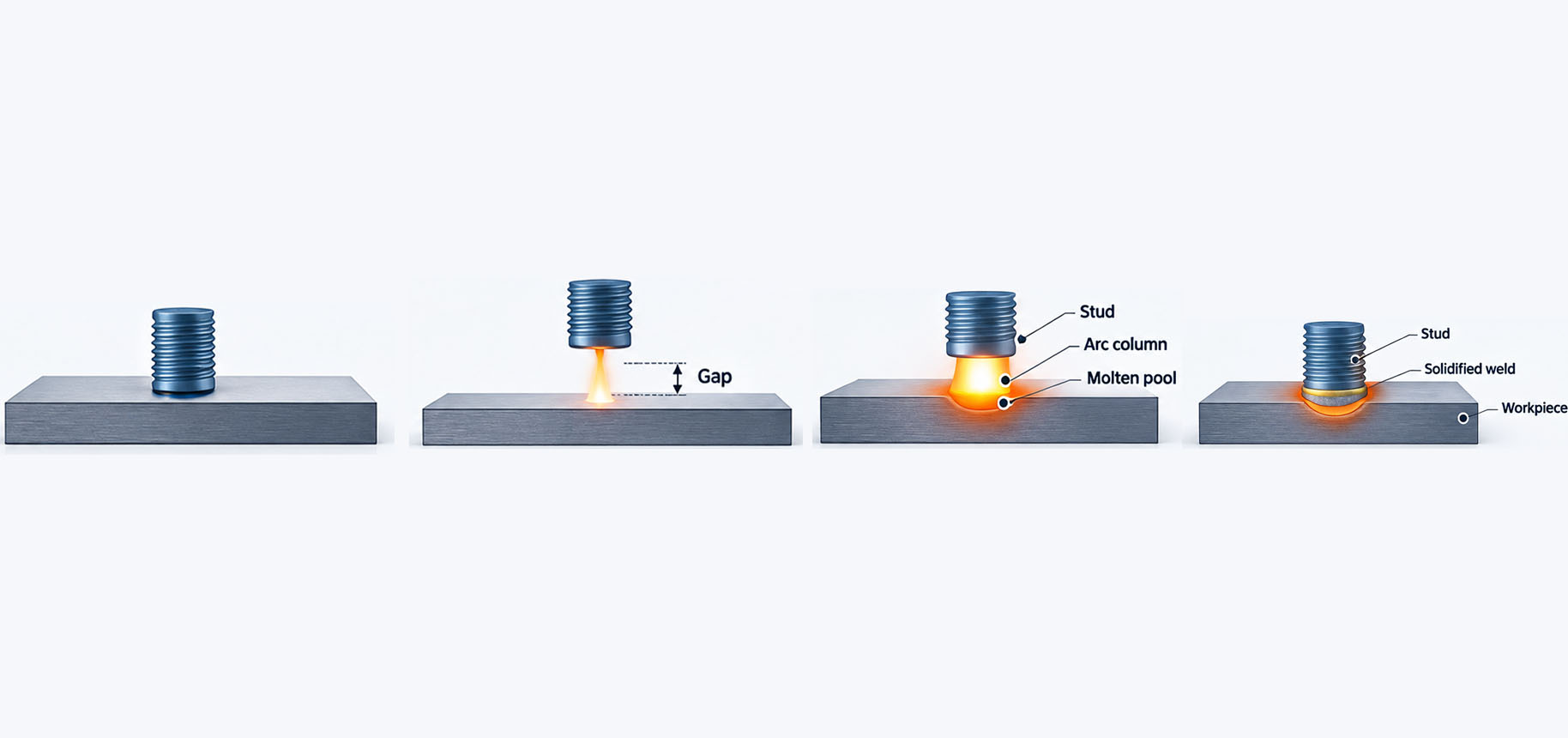
The welding cycle progresses from initial contact to arc initiation, main welding and plunge.
Stage 1: Initial contact
The stud is positioned against the workpiece, creating the electrical contact required to initiate the welding sequence. Consistent positioning and stable contact help establish repeatable starting conditions.
Stage 2: Pilot arc
The power source applies the pilot current while the servo welding gun lifts the stud away from the workpiece. This establishes the pilot arc before the main welding stage begins.
The pilot stage helps initiate the arc and prepare for the main welding cycle. On coated or contaminated surfaces, the results also depend on the coating, surface cleanliness, and the selected current and time.
Stage 3: Main welding arc
When the stud reaches the preset lift height, the power source delivers the main welding current for the programmed duration. The arc melts the end of the stud and the corresponding area of the base material, forming a molten pool.
The servo gun then drives the stud toward the workpiece and into the molten pool. The relationship between current, welding time, lift height, and stud movement determines how the joint forms.
Stage 4: Plunge and post-welding current control
Depending on the programmed sequence, the equipment may provide a separately controlled current stage during or after the stud’s plunge into the molten pool.
The exact function of this stage depends on the SAW-3600 control configuration. The term upset current should therefore be used only if it matches the parameter’s actual function in the equipment documentation. It should not be confused with the mechanical plunge movement itself.
2. Pilot Current and Pilot Time
Pilot current and pilot time affect the beginning of the welding cycle. If the arc does not start consistently, changing the main welding current may not solve the underlying problem.
Pilot current is the current applied during the pilot arc stage. Pilot time determines how long that stage lasts.
For galvanized steel, the coating and surface condition can influence arc initiation. Oil, dirt, and other contaminants may also affect consistency. However, a higher pilot current or a longer pilot time is not automatically better. The aim is to establish a stable arc without introducing unnecessary heat.
Equipment settings
| Parameter | Minimum | Default | Maximum | Unit |
|---|---|---|---|---|
| Pilot time | 10 | 50 | 100 | ms |
| Pilot current | 15 | 50 | 150 | 一个 |
The default pilot current is 50 A, and the default pilot time is 50 ms for the configuration described here.
These values provide a starting point rather than a fixed recommendation for every application. When adjustment is needed, consider pilot current and pilot time together. Make controlled changes and observe whether arc initiation becomes more consistent.
3. Welding Current and Welding Time
Once the main arc is established, welding current and welding time become the principal electrical parameters controlling the melting process.
Welding current determines the current delivered during the main welding stage, while welding time determines how long it is applied. Their combined effect influences the melting of the stud end and base material, the size of the molten pool, and the resulting weld profile.
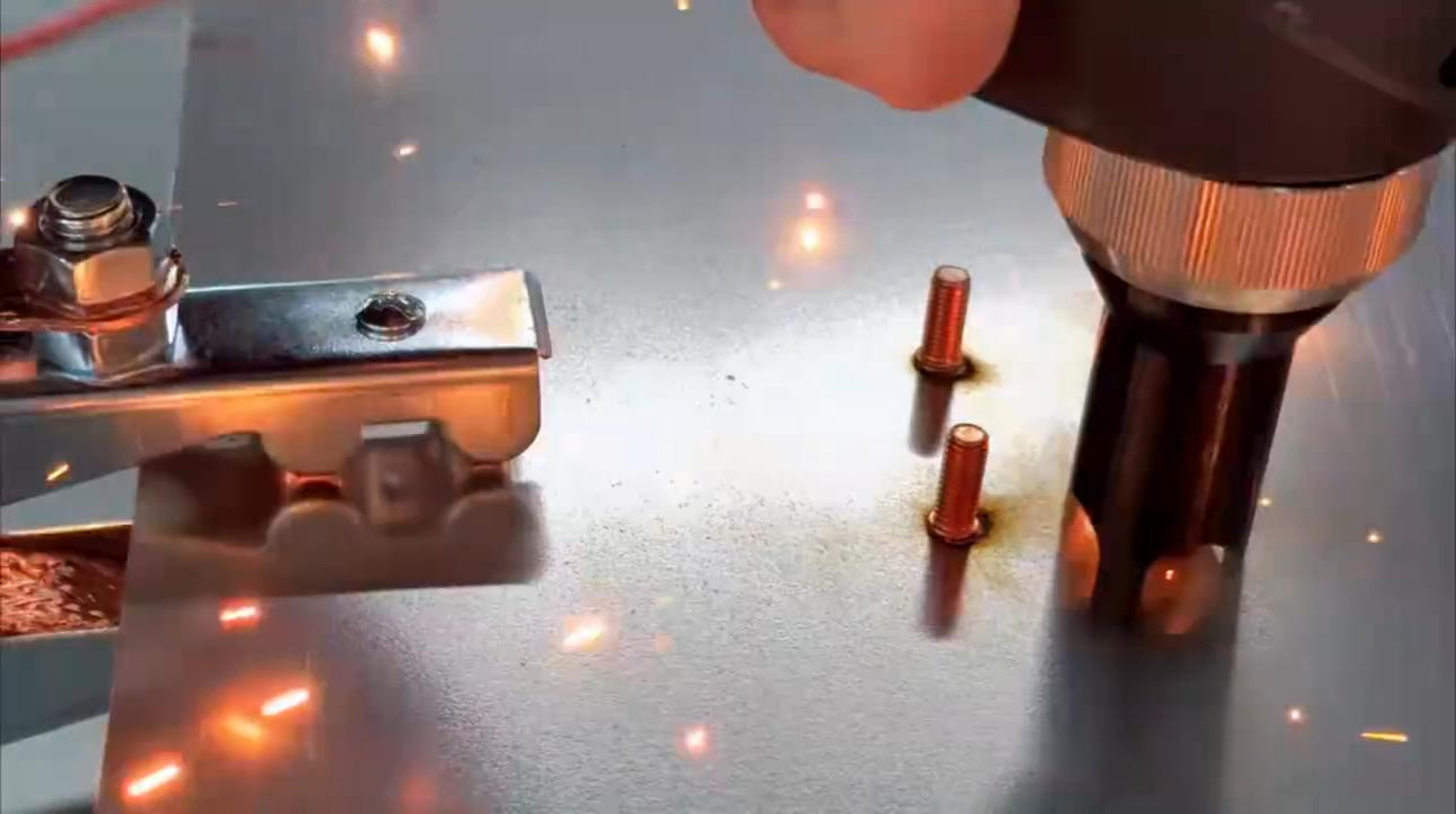
Main welding current and duration determine the energy delivered to the stud and workpiece.
If the energy input is too low, the stud may not fuse adequately with the workpiece. If it is too high, the weld may produce excessive spatter or an oversized collar. Thin sheet metal is particularly sensitive to excessive heat input.
Equipment settings
| Parameter | Minimum | Default | Maximum | Unit |
|---|---|---|---|---|
| Welding time | 5 | 20 | 100 | ms |
| Welding current | 100 | 300 | 2,000 | 一个 |
The values above describe the available settings for the equipment configuration covered by this guide. The appropriate working values depend on the stud and the actual welding application.
Using stud diameter as an initial reference
For preliminary trials, the following empirical relationships can provide a starting point:
Estimated welding current
Welding current ≈ Stud diameter (mm) × 100 A
For a 6 mm stud:
6 × 100 = 600 A
This gives an initial reference of approximately 600 A.
Estimated welding time
Welding time ≈ Stud diameter (mm) × 3–5 ms
For a 6 mm stud:
6 × 3–5 = 18–30 ms
A starting trial value near 24 ms may be appropriate, depending on the material and equipment configuration.
These formulas are practical estimates, not universal rules. Two applications using the same stud diameter may require different settings because of differences in material, sheet thickness, stud-end geometry, surface coating, and arc conditions.
When developing a welding procedure, change the current or time in controlled increments and compare the results. Adjusting several parameters at once makes it much harder to identify what actually improved or worsened the weld.
4. Upset Time and Upset Current
Upset time and upset current are available on certain welding systems, but their functions depend on the equipment’s control sequence.
Upset time refers to the duration of the designated stage. Upset current refers to the current applied during that stage, where independent current control is supported.
These terms should be checked against the actual equipment configuration. In particular, a separately controlled current during stud plunge is not necessarily the same as a post-welding holding current.
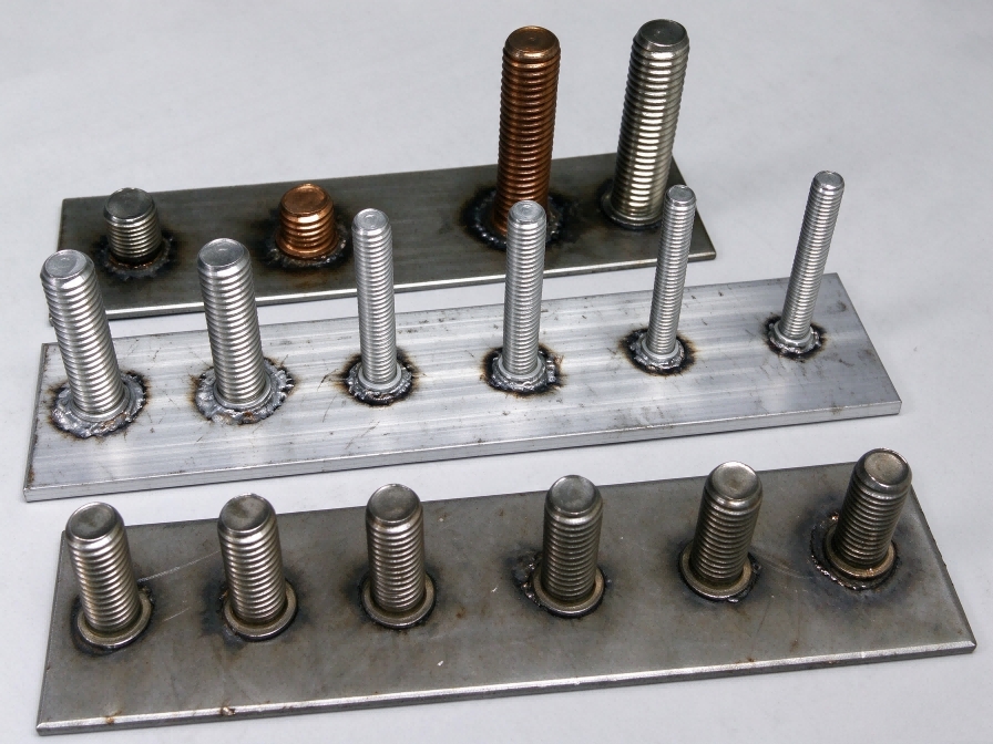
The finished weld should be assessed alongside the selected process settings and the application requirements.
Equipment settings
| Parameter | Minimum | Default | Maximum | Unit |
|---|---|---|---|---|
| Upset time | 0 | 5 | 20 | ms |
| Upset current | 100 | 200 | 1,500 | 一个 |
Reference settings for different applications
The following values are preliminary references supplied for this guide. They should be verified through trial welding before being used in production.
| Application | Reference Upset Time | Reference Upset Current |
|---|---|---|
| T-type stud | 3 ms | — |
| Thin sheet metal (≤ 0.8 mm) | 5 ms | 100–200 A |
| Studs M5 and larger | 6–8 ms | 200–300 A |
| General reference, depending on stud size | 5–12 ms | — |
The general reference of 5–12 ms is not the same as the equipment’s default setting of 5 ms or its available range of 0–20 ms. The first is an application guideline; the others describe the equipment settings.
When evaluating these parameters, look at the complete weld rather than a single visual feature. Stud alignment, weld collar formation, spatter, sheet deformation, and joint strength all matter. A weld that looks acceptable on the surface may still require mechanical testing to confirm its integrity.
5. Reference Parameters for Common Stud Types
The following table lists the reference combinations provided for several stud types.
| Stud Type | Low Current (A) | Low-Current Time (ms) | High Current (A) | High-Current Time (ms) |
|---|---|---|---|---|
| T-type stud | 35 | 30 | 220 | 15 |
| M5 stud | 35 | 30 | 450 | 22 |
| M6 stud | 35 | 30 | 600 | 26 |
| M6 large-cap stud | 50 | 50 | 800 | 40 |
These values are intended as references for the corresponding equipment and application, not as universal settings for all stud welding systems.
The labels low current and high current follow the supplied reference data. They should not automatically be interpreted as pilot current and main welding current without confirmation from the original equipment documentation.
Before using these settings, check the stud geometry, base material, sheet thickness, lift height, and operating mode. During commissioning, begin with a suitable reference procedure and make gradual adjustments. Trial welds should be inspected before the settings are accepted for production.
6. Lift Height and Target Arc Voltage
Current and welding time are only part of the process. Lift height and target arc voltage also affect arc conditions and should be considered when troubleshooting inconsistent welds.
Lift height
Lift height is the distance the welding gun raises the stud from the workpiece to establish the arc gap.
The reference setting range is 0.5–4 mm, with 1–1.5 mm suggested as an initial reference where appropriate.
An unsuitable lift height can affect arc stability and weld formation. Increasing the lift height does not necessarily improve the result, so it should be evaluated alongside the current, welding time, stud geometry, and control mode.
Target arc voltage
For equipment operating in a constant-power control mode, target arc voltage is one of the parameters used to regulate the welding process.
The reference range provided for this guide is 20–26 V. This should not be treated as a universal setting for every power source or application. The appropriate value depends on the equipment design, control algorithm, stud type, and welding conditions.
When adjusting lift height or target arc voltage, compare the actual weld results rather than relying on the setpoint alone.
7. A Practical Approach to Parameter Optimization
Parameter adjustment should be followed by test welding and verification of the finished joint.
A good starting point is to confirm the stud specification, base material, sheet thickness, surface coating, and required joint strength. These details help determine which reference procedure is appropriate.
Next, establish initial settings using the equipment manual and available process data. Conduct trial welds on representative workpieces under stable conditions, changing one parameter at a time wherever practical.
Inspect the resulting welds for stud alignment, collar consistency, excessive spatter, deformation, and burn-through. Where required, use mechanical testing or other suitable inspection methods to verify joint integrity.
Once an acceptable parameter combination has been established, record the settings together with the material conditions, equipment configuration, and inspection results. Repeat the trials under representative production conditions to check that the results remain consistent across multiple welds.
At Hongbai Technology, we develop stud welding equipment and intelligent welding automation solutions for industrial manufacturing. Our SAW-3600 series is part of our stud welding equipment portfolio, supporting applications where reliable process control and repeatable weld quality are important.