
How position, velocity, and current control work together to achieve precise, repeatable gun motion.
In automated 螺柱焊接, the welding gun must reach programmed positions, follow a defined motion profile, and respond quickly to changes in mechanical load. These requirements are managed by a cascaded three-loop servo control architecture: the position loop, velocity loop, and current loop.
Hongbai’s servo control architecture combines MCU and FPGA processing to coordinate motion commands, feedback regulation, and gun movement throughout the welding cycle.
1. The Three Loops of Servo Control
Position Loop: Accurate Positioning
The outermost loop controls the position of the gun’s lifting mechanism using feedback from a high-resolution optical linear encoder.
Its main functions are to track commanded positions, reduce positioning errors, and maintain the required position during designated stages of the welding cycle.
Accurate positioning helps ensure that the gun follows the programmed movement sequence and establishes the intended lift conditions for the welding process.
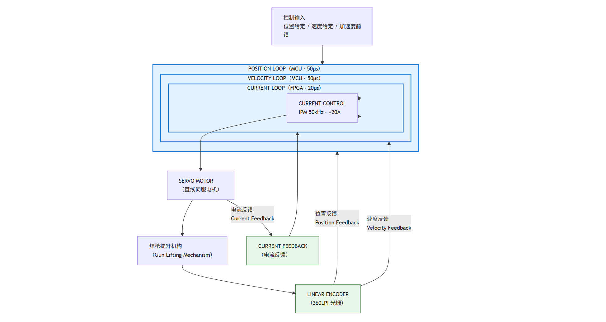
The position, velocity, and current loops work together to regulate positioning accuracy, motion tracking, and motor torque response.
Velocity Loop: Motion Profile Tracking
The velocity loop regulates motor speed according to the trajectory generated by the motion planner. Velocity feedback, derived from position measurements or dedicated estimation, enables the controller to correct tracking errors.
The specified motion configuration includes:
- Maximum velocity: adjustable range of approximately 50–800 mm/s (recommended 400 mm/s)
- Acceleration: adjustable range of approximately 20–80 m/s² (recommended 50 m/s²)
These are application-specific settings. Actual motion performance depends on the gun mechanism, moving mass, stroke, and load conditions.
Current Loop: Fast Torque Response
The innermost loop regulates servo motor phase current, which is closely related to motor torque. It enables the drive to respond to acceleration commands and changes in mechanical load.
The specified servo-drive parameters are:
| Parameter | Value |
|---|---|
| Current-loop control period | 20 μs |
| Switching frequency | 50 kHz |
| Maximum current command/output | ±20 A |
| Specified current response | 10 A within 40 μs |
These figures apply to the specified drive configuration and should be verified against its technical documentation.
Servo motor current is different from welding current. Motor current controls the gun’s movement; welding current supplies the energy required to form the weld. The two systems must be coordinated but perform different functions.
2. MCU + FPGA Control Architecture
The three loops have different processing requirements. Hongbai’s specified architecture distributes them between an MCU and an FPGA.
| Control function | Hardware | Control period |
|---|---|---|
| Position loop | MCU | 50 μs |
| Velocity loop | MCU | 50 μs |
| Current loop | FPGA | 20 μs |
| Motor power-stage switching | FPGA-based control and IPM | 50 kHz |
The MCU executes position and velocity regulation in synchronization with the welding controller. The FPGA handles the faster current loop, enabling a shorter current-control interval.
This division supports coordinated motion control while allowing the motor-current regulation stage to respond more rapidly to torque demands.
3. Motion Planning and Feedback
The motion planner uses T-profile motion planning and interpolation at a specified 50 μs interval.
It generates three reference signals:
- Position command: Defines the target position.
- Velocity command: Defines the desired movement speed.
- Acceleration feedforward: Helps anticipate the torque demand associated with planned acceleration.
The servo controller monitors position, velocity, and motor-current feedback to regulate actual movement against these commands.
This combination of trajectory planning and closed-loop feedback helps the gun follow the intended motion profile while responding to real operating conditions.
4. Four Stages of Gun Motion
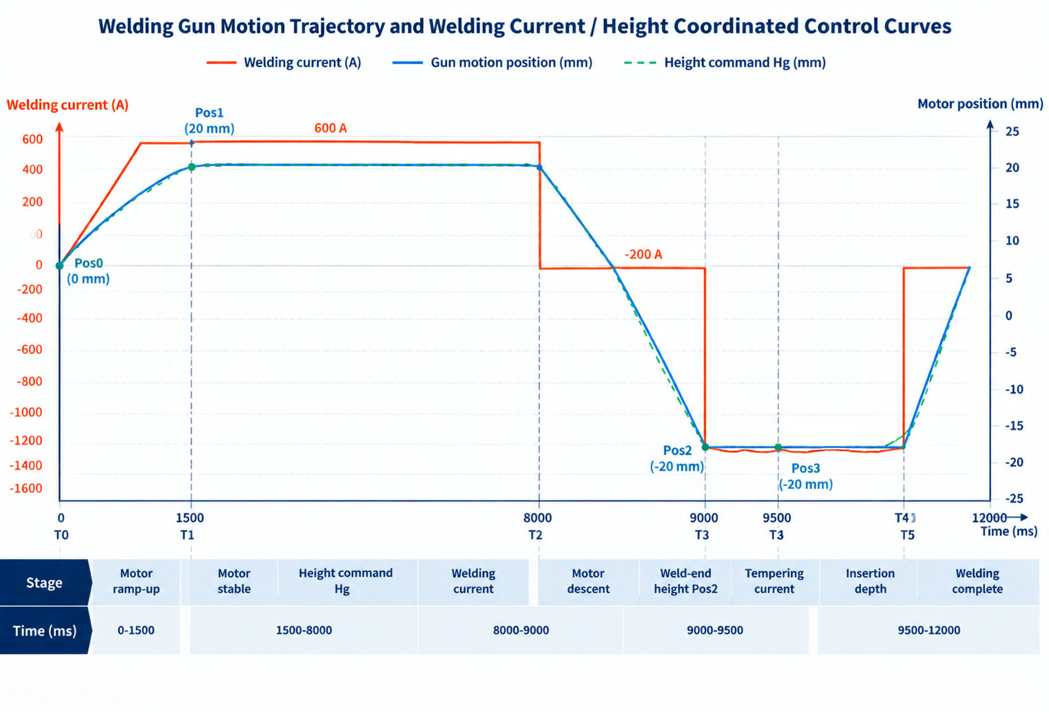
The programmed motion profile defines the gun’s movement between target positions and the timing of each holding stage.
The specified motion sequence consists of four stages:
- Pos0 to Pos1: The gun moves to the first programmed position using a T-profile, with a specified acceleration of approximately 30 m/s².
- Hold at Pos1: The controller maintains the commanded position.
- Pos1 to Pos3: The gun follows the next motion profile, with acceleration of approximately 50 m/s² (about 5.1 g) and a maximum velocity of 400 mm/s.
- Hold at Pos3: The gun maintains its commanded position for the required stage of the welding sequence.
Throughout these stages, the servo controller regulates gun motion while the welding controller coordinates the relevant welding events. The exact timing depends on the configured welding process.
5. Waveform Monitoring and Fault Diagnosis
Recorded servo signals help engineers evaluate tracking performance, investigate abnormal movement, and troubleshoot the gun mechanism.
Hongbai’s specified HEAS configuration includes waveform recording for position error, velocity tracking, motor current, and current error.
| Monitored signal | Potential indication |
|---|---|
| Position error | Incorrect tuning, excessive load, or mechanical resistance |
| Velocity tracking | Motion-profile mismatch or abnormal mechanical load |
| Motor current | Increased friction or restricted gun movement |
| Current error | Servo tracking issues, mechanical resistance, or potential drive-related faults |
The specified configuration includes example diagnostic thresholds of:
- Motor current ≥15 A sustained for approximately 5 ms.
- Current error ≥2 A sustained for approximately 5 ms.
These are configuration-specific thresholds, not universal fault limits. A single signal cannot conclusively identify a fault; engineers should correlate recorded data with the commanded motion, operating stage, and mechanical condition.
Waveform analysis can support commissioning, parameter tuning, and maintenance by showing how the gun responds under actual operating conditions.
Engineering Considerations for Automated Welding
Servo performance depends on more than encoder resolution or motor response. Motor sizing, motion-profile tuning, mechanical resistance, gun alignment, and welding-cycle timing all affect the final result.
For automated production, the objective is to achieve repeatable gun motion and reliable coordination with the welding process. Weld quality must still be validated against the application-specific materials, welding parameters, and process requirements.
At Hongbai Technology, servo control is part of the engineering behind our automated stud welding solutions. We develop stud welding equipment and integrated welding systems for automotive manufacturing and other industrial applications, with a focus on precise motion control, process consistency, and reliable production performance.
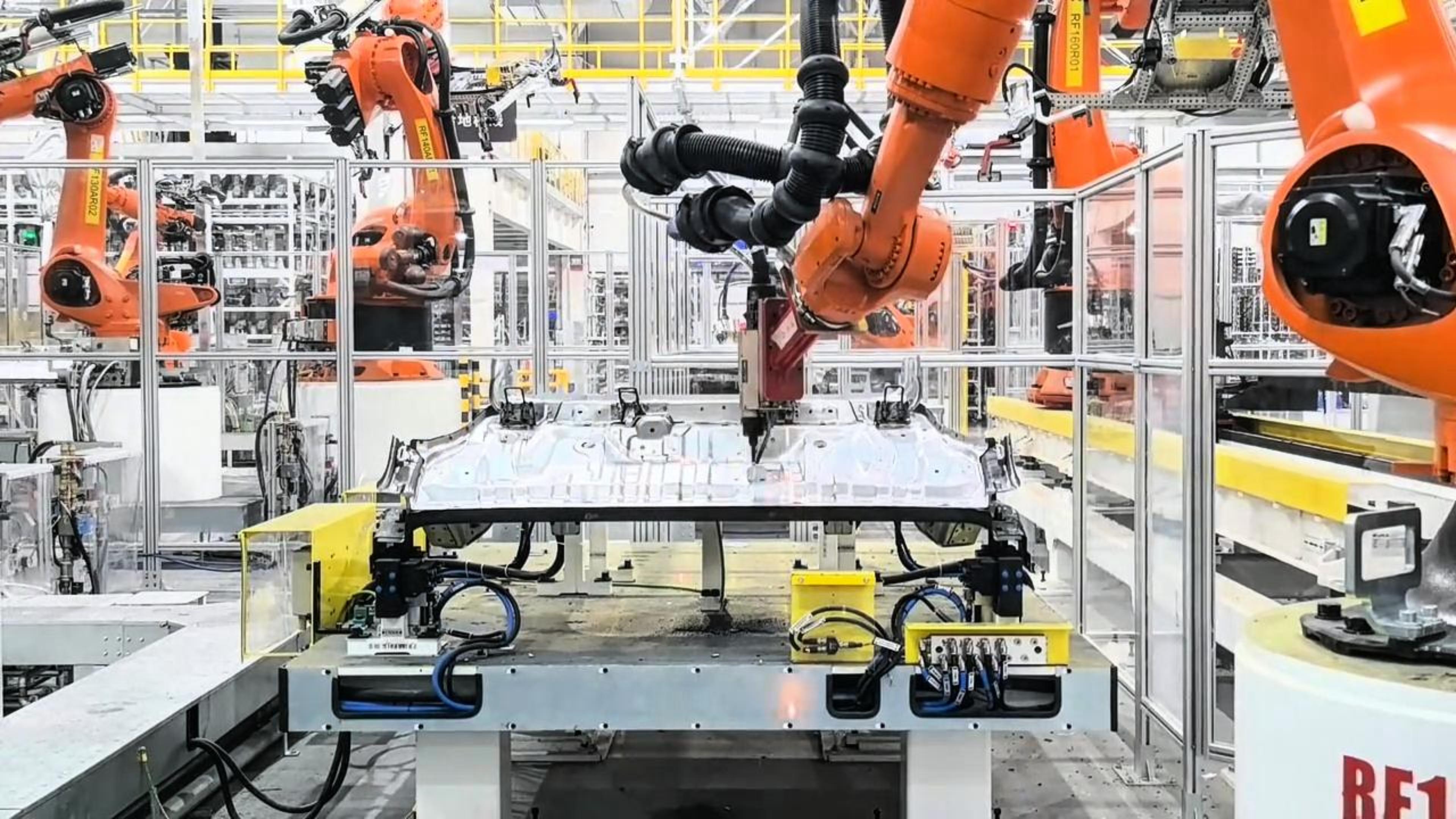
Automated stud welding solutions for automotive and industrial manufacturing.
Looking for a Stud Welding Solution?
Hongbai Technology provides stud welding equipment and automated welding solutions for automotive and industrial applications.
Contact Hongbai to discuss your stud welding requirements and automation projects.