

1. Stud Welding in Sheet Metal Electrical Enclosure Manufacturing
Stud welding is widely used for fastening applications in electrical enclosures, control cabinets, switchgear cabinets, distribution boxes, and other sheet metal structures. Compared with conventional nut welding, drilling and tapping, or mechanical fastening, stud welding allows a threaded stud or fastening element to be permanently attached directly to the sheet metal surface, reducing additional machining and assembly operations.
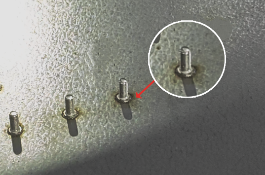
Typical applications include grounding studs, mounting studs for circuit breakers and terminal blocks, busbar supports, cable management components, door hardware, and other internal cabinet components.
In practical production, the selection of a sheet metal stud welding process depends mainly on sheet thickness, stud diameter, base material, required joint strength, surface condition, and the appearance requirements of the opposite side of the workpiece.
For thin sheet metal electrical enclosures, minimizing distortion, discoloration, and visible marks on the reverse side can be particularly important. For structural components and grounding connections, weld strength and process consistency may take priority.
Therefore, selecting stud welding equipment for electrical enclosures requires more than simply checking the welding current or stud diameter. The welding power source, stud welding gun, stud feeder, workholding system, and level of automation all need to be considered as part of the same process.
2. Capacitor Discharge and Drawn Arc Stud Welding
2.1 Capacitor Discharge Stud Welding
Capacitor discharge (CD) stud welding stores electrical energy in capacitors and releases it over an extremely short welding cycle.
Typical welding time is approximately 0.001–0.003 seconds, with peak current reaching approximately 5,000–10,000 A. Because the welding cycle is extremely short, heat input is concentrated around the weld area.
This makes capacitor discharge stud welding particularly suitable for thin sheet metal and applications where backside appearance is important.
Hongbai’s PFC Series capacitor discharge stud welding machines support stud diameters from 2 to 10 mm and can be used with low-carbon steel, stainless steel, aluminum, copper, and zinc materials.
2.2 Drawn Arc Stud Welding
Drawn arc stud welding creates an arc between the stud and the workpiece before the stud is plunged into the molten weld pool.
Typical welding current is approximately 1,500–2,000 A, while welding time generally falls within 5–100 ms, depending on stud diameter, material, and process parameters.
Compared with capacitor discharge welding, drawn arc stud welding generally provides deeper penetration and higher joint strength. It is therefore commonly considered for structural components, grounding studs, and applications where mechanical strength is a primary requirement.
3. Selecting the Right Stud Welding Process for Electrical Enclosures
| Application | Recommended Process | Main Consideration |
|---|---|---|
| Thin sheet metal panels | Capacitor discharge | Low heat input, reduced backside marking |
| Exterior enclosure panels | Capacitor discharge | Surface appearance and dimensional stability |
| Internal structural components | Drawn arc | Higher joint strength |
| Grounding studs | Drawn arc / CD | Material and strength requirements |
| High-volume production | Automatic stud welding | Productivity and repeatability |
For sheet metal in the range of approximately 0.4–1.0 mm, capacitor discharge stud welding is often considered when controlling heat input and backside marking is important.
For thicker structural components, drawn arc stud welding can be evaluated when higher joint strength and deeper fusion are required.
The actual process should always be validated according to sheet thickness, stud diameter, stud material, surface condition, and joint design, rather than selecting the process based on sheet thickness alone.
4. Stud Welding Equipment Selection
When selecting a stud welding machine for electrical enclosures, the maximum welding current is only one of the parameters to consider. Charging capacity, welding time, output control, stud diameter range, welding gun configuration, and automatic stud feeding capability can all affect the suitability of the system.
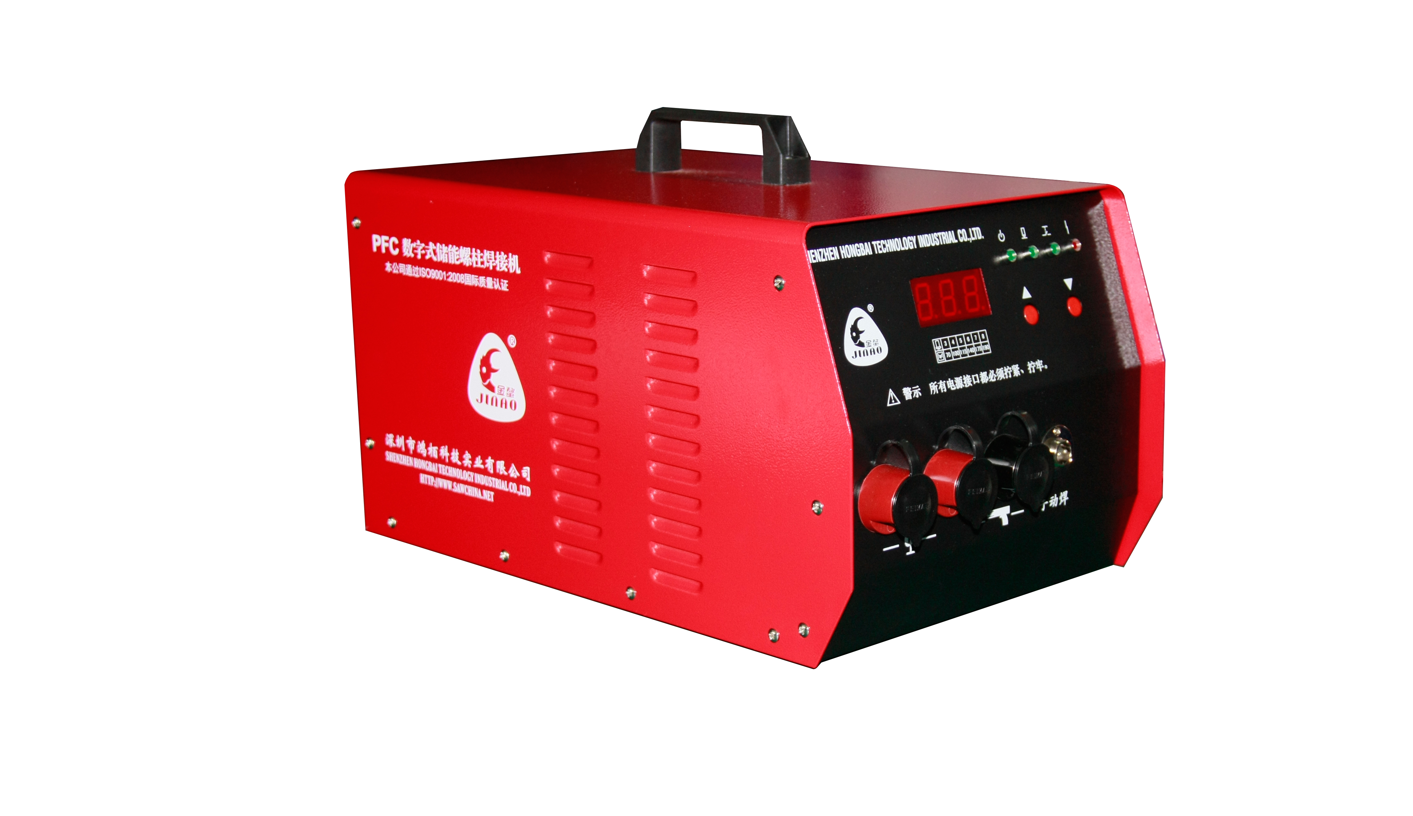
Hongbai’s PFC Series capacitor discharge stud welding machines are designed for CD stud welding applications.
| Parameter | PFC-08 | PFC-12 |
|---|---|---|
| Input Power | 350 W | 500 VA |
| Charging Voltage | 25–200 VDC | 35–200 VDC |
| Capacitor Capacity | 108,000 μF | 108,000 μF |
| Welding Time | 0.001–0.003 s | 0.001–0.003 s |
| Stud Diameter | 2–10 mm | 2–10 mm |
| Workpiece Thickness | 0.2–10 mm | 0.2–10 mm |
| Welding Materials | Low-carbon steel, stainless steel, aluminum, copper, zinc | Low-carbon steel, stainless steel, aluminum, zinc |
| Welding Efficiency | Up to 20–40 studs/min | Up to 30–40 studs/min |
| Input Voltage | 220 VAC ±10% | 110/220 VAC |
| Protection Rating | IP31 | IP31 |
| Weight | 20 kg | 24.5 kg |
The PFC series supports manual contact/gap welding and automation, with voltage/current monitoring, overcurrent protection, and temperature sensing. For drawn‑arc welding, the SAW‑3600 Series handles 3–12 mm studs at 1,800 A max, with optional multiple independent channels. The fifth‑generation HEAS/HEDS systems feature 50 kHz inverter and 100 kHz digital current loop, achieving 1,500 A/0.34 ms ramp‑up, plus data logging, quality analysis, and industrial comms.
5. Welding Parameters That Affect Stud Welding Quality
Stud welding quality is determined by the interaction of several process parameters rather than by welding current alone.
For drawn arc stud welding, important parameters include:
- Pilot current
- Pilot time
- Welding current
- Welding time
- Lift height
- Arc voltage
- Plunge current
- Plunge time
For the SAW-3600 Series, the adjustable parameter ranges include:
| Parameter | Adjustment Range | Resolution |
|---|---|---|
| Pilot Current | 15–150 A | 1 A |
| Pilot Time | 10–100 ms | 1 ms |
| Welding Current | 100–1,800 A | 1 A |
| Welding Time | 5–100 ms | 1 ms |
| Plunge Current | 100–1,500 A | 1 A |
| Plunge Time | 0–20 ms | — |
| Lift Height | 0.5–4.0 mm | 0.05 mm |
| Expected Arc Voltage | 10–40 V | 1 V |
For common steel sheets, set the initial welding current to roughly the stud diameter in millimeters multiplied by 100 A. For an M6 stud, start at about 600 A. Welding duration can be estimated as 3 to 5 milliseconds per millimeter of diameter, giving 18 to 30 ms.
Pilot current begins around 50 A, and arc voltage is typically tested between 20 and 26 V. These values serve only as a starting point; before production, verify them against sheet thickness, stud material, surface condition, and joint design. For galvanized steel, adjust pilot parameters and voltage to compensate for the coating’s effect on arc stability.
6. Automatic Stud Feeding for Electrical Cabinet Production
As production moves from manual stud welding toward automatic stud welding, the stud feeding system becomes an important part of overall process stability.
A typical automatic stud feeding sequence is:
Stud sorting → Stud feeding → Stud delivery → Stud loading → Stud welding
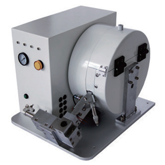
The feeder needs to work consistently with the welding gun and power source. Feeding interruptions, misfeeds, or incorrect stud orientation can directly affect production cycle time.
Hongbai’s FRS Series automatic stud feeders are available for different stud welding configurations.
For example, the FRS30 provides:
| Parameter | FRS30 |
|---|---|
| Operating Mode | Automatic / Manual / Test |
| Air Pressure | 0.5–0.8 MPa |
| Stud Capacity | 1,000–3,000 pcs |
| Feeding Speed | 30–60 pcs/min |
| Supply Voltage | AC 220 V ±15% |
| Operating Temperature | -10°C to 40°C |
| Communication | I/O |
| Dimensions | 405 × 340 × 330 mm |
| Weight | 40 kg |
7. CNC Stud Welding for Sheet Metal Electrical Enclosures
For high-volume production where enclosure dimensions and stud locations are relatively standardized, a CNC stud welding machine can provide a practical approach to automated positioning and repeatable welding.
Hongbai’s SAW-Z CNC stud welding platform can be configured according to workpiece dimensions, welding point quantity, welding gun configuration, and production requirements.
| Model | X Travel | Y Travel | Typical Application |
|---|---|---|---|
| SAW-Z0806 | 800 mm | 600 mm | Small electrical boxes |
| SAW-Z1008 | 1,000 mm | 800 mm | Medium electrical cabinets |
| SAW-Z1215 | 1,200 mm | 1,500 mm | Large electrical cabinets |
| SAW-Z1322 | 1,300 mm | 2,200 mm | Extra-large cabinets |
The platform can be configured for capacitor discharge or drawn arc stud welding and can support 1–6 welding guns, depending on the system configuration.
The X/Y axes can use precision linear motion components with 1 μm magnetic scale feedback. Positioning accuracy can reach approximately ±0.05 mm under the specified configuration.
DXF drawing files can be imported to define stud welding positions. Welding points can then be automatically arranged according to X-axis, Y-axis, or counterclockwise sequencing.
8. Robotic Stud Welding for Flexible Production
When electrical enclosure production involves multiple cabinet sizes, frequent product changes, or integration with an existing automated production line, robotic stud welding can provide greater flexibility.
A typical robotic stud welding cell consists of:
Robot + Stud Welding Power Supply + Automatic Stud Feeder + Servo Stud Welding Gun + Fixture
The robot controls movement and positioning, while the welding power source controls the welding process and the feeder provides studs to the welding gun.
During system integration, the following points should be defined before commissioning:
- Robot communication protocol
- I/O configuration
- Welding gun positioning
- Stud feeding route
- Fixture positioning
- Safety interlocks
- Emergency stop circuit
Depending on the system configuration, Hongbai stud welding systems can support industrial communication protocols including DeviceNet, PROFIBUS, PROFINET, EtherNet/IP, EtherCAT, and Modbus TCP.
The fifth-generation servo welding guns use a servo linear motor drive with a position resolution of 5 μm and an 8 mm motor stroke. Automatic configurations support 3–12 mm studs and can incorporate stud detection and position-limit monitoring.
9. Stud Welding Quality Control for Electrical Enclosures
For sheet metal electrical enclosure production, quality control normally combines visual inspection, mechanical testing, and process monitoring.
Visual Inspection
The weld collar should be continuous and reasonably uniform. Typical defects to check include:
- Incomplete fusion
- Excessive spatter
- Cracks
- Porosity
- Uneven weld collar
- Stud misalignment
- Tensile and Bend Testing
Stud tensile testing and bend testing can be used to evaluate joint integrity.
In tensile testing, the stud is subjected to axial loading until failure. A failure occurring outside the weld zone generally indicates that the welded joint has achieved the required strength.
Bend testing can be used to evaluate whether cracking or fracture occurs in the weld zone under the specified bending condition.
Process Monitoring
For automated production, final inspection alone does not provide sufficient information about process variation.
The HEAS/HEDS system can record welding current, voltage, and welding waveforms and use SPC (Statistical Process Control) to monitor changes in the welding process.
The SAW-3600 Series also incorporates AQC2 Active Quality Control, which uses process feedback to reduce the influence of external disturbances such as workpiece position variation.
10. Selecting the Right Level of Stud Welding Automation
Different electrical enclosure production models require different levels of automation.
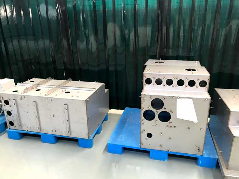
Manual Stud Welding
Suitable for low-volume production, frequent product changes, repair work, and rework.
Automatic Stud Feeding
A practical step when the objective is to reduce manual stud loading and improve continuous production.
CNC Stud Welding
Suitable for standardized electrical enclosures with repetitive stud locations and relatively high production volumes.
Robotic Stud Welding
More suitable for high product variety, flexible production, and integration with existing robotic manufacturing lines.
The highest level of automation is not necessarily the best solution for every manufacturer. Production volume, product variety, number of studs per workpiece, changeover frequency, cycle time, and existing equipment should all be considered before defining the automation architecture.
Practical Considerations for Electrical Enclosure Stud Welding
For sheet metal electrical enclosure manufacturing, stud welding equipment selection is closely related to the welding process, base material, sheet thickness, stud diameter, required joint strength, and production volume.
For thin exterior panels where backside appearance is important, capacitor discharge stud welding can be evaluated because of its short welding cycle and concentrated heat input. For structural components, grounding connections, and applications requiring higher joint strength, drawn arc stud welding may be more appropriate.
As production requirements increase, automatic stud feeding, CNC positioning, and robotic stud welding can be introduced according to the actual production needs.
In practice, a stable stud welding process is rarely determined by a single machine parameter. The welding power source, welding gun, stud feeder, workholding fixture, positioning accuracy, and process monitoring all contribute to welding consistency.
For electrical enclosure manufacturers, establishing the welding process first and then selecting the appropriate equipment and automation level is generally a more practical way to build a repeatable production process.
If you are planning a stud welding process or automation solution for electrical enclosures and sheet metal components, explore Hongbai’s stud welding equipment and technology solutions for more information.
👉LinkedIn: