


Introduction
In automotive Body-in-White (BIW), automotive components, and new energy vehicle structural manufacturing, stud welding is widely used for applications such as cable harness fixing, heat shield installation, interior component mounting, and structural part assembly.
However, in actual production, issues such as poor weld integrity, porosity, slag inclusion, and incomplete fusion remain key factors affecting stud welding quality stability.
In severe cases, these defects can reduce stud strength and even cause stud detachment, affecting downstream assembly processes and product reliability.
Based on stud welding principles and practical industrial applications, this article systematically analyzes the formation mechanisms, major causes, and engineering solutions for porosity and slag inclusion defects.
1. Formation Mechanism of Porosity and Slag Inclusion
1.1 Porosity Formation Mechanism:
During the stud welding process, the high-temperature arc rapidly melts the welding area and forms a weld pool.
If gases (such as H₂, CO, and N₂) inside the weld pool cannot escape before the molten metal solidifies, they will remain trapped inside the weld and form porosity.
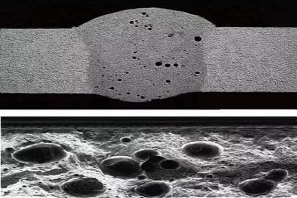
Porosity is mainly classified into:
- Surface porosity
- Internal porosity
Among them, internal porosity is more difficult to detect and can reduce the effective strength of the welded joint.
1.2 Slag Inclusion Formation Mechanism:
Slag inclusion refers to non-metallic impurities generated during the welding process that fail to escape in time and remain trapped inside the weld after solidification, forming defects.
The main sources include:
- Oxides on the base material surface
- Oil contamination and foreign materials
- Coating residues
- Oxidation products generated during the welding process
Slag inclusion reduces the effective bonding area of the weld and creates stress concentration areas, affecting weld joint reliability.
2. Six Root Causes of Porosity and Slag Inclusion
2.1 Workpiece Surface Contamination — The Most Common Cause
Insufficient cleaning before welding is the primary cause of porosity and slag inclusion. If contaminants such as oil, rust, anti-rust oil, zinc coating, or paint exist on the workpiece surface, these contaminants will decompose under high welding temperatures and generate gases (such as H₂ and CO). If these gases cannot escape from the weld pool in time, porosity will occur. Meanwhile, oxide residues generated from the decomposition of contaminants may also form slag inclusion.
- When the anti-rust oil thickness exceeds 10 μm, a large amount of porosity may occur, increasing the risk of incomplete fusion defects.
- During galvanized steel stud welding, zinc has a boiling point of 907℃, which is lower than the melting point of steel (approximately 1538℃). Zinc vaporizes first and enters the weld pool. If gas escape is insufficient, zinc vapor may form concentrated porosity.
- Iron oxide generated from surface corrosion may be reduced under high temperatures and produce CO gas, resulting in porosity.
Solutions:
Three-step surface preparation process before welding:
First, clean the surface with a degreasing agent → then remove surface oxides and contaminants using a wire brush or abrasive paper → finally wipe the surface with a clean cloth.
For workpieces with severe oil contamination, laser cleaning can be applied, with efficiency up to three times higher than chemical cleaning.
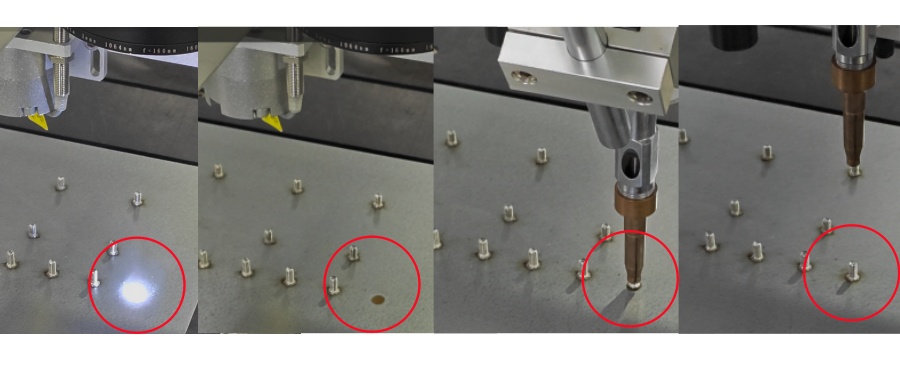
For stud welding on galvanized steel sheets, it is recommended to control the zinc coating thickness within 15 μm. The arc initiation current and arc initiation time can be appropriately increased to utilize the arc initiation pulse to remove the surface zinc coating.
Oxides on the stud end face should be removed using a wire brush or abrasive paper.
2.2 Incorrect Welding Parameter Matching — Improper Heat Input
Insufficient or excessive welding heat input can both lead to porosity and slag inclusion.
- Welding current too low or welding time too short: Insufficient heat input results in a short molten pool lifetime. Gases cannot escape in time and become trapped, causing porosity.
- Welding current too high or welding time too long: Excessive heat input overheats the weld pool, causing intense metal boiling and increased gas entrapment. Meanwhile, excessive alloy element oxidation increases the formation of oxide slag inclusions.
- Incorrect lift height: When the arc length is too long, arc stability decreases and air can easily enter the weld pool, causing porosity. When the arc length is too short, insufficient molten pool agitation prevents impurities from floating and being removed effectively.
Solutions:
Adjust welding parameters according to the recommended standard parameter range (taking drawn arc stud welding as an example):
| Stud Diameter (mm) | Arc Welding Current (A) | Welding Time (s) | Lift Height (mm) |
|---|---|---|---|
| 4 | 200-300 | 0.4-0.6 | 0.6-0.8 |
| 6 | 300-450 | 0.5-0.7 | 1.0-1.4 |
| 8 | 400-600 | 0.6-0.8 | 1.2-1.6 |
| 10 | 600-800 | 0.7-1.0 | 1.6-2.0 |
Actual adjustment method:
Use welding current as the primary reference and gradually optimize the parameters.
In stud welding, welding energy can be approximately expressed as:
Energy ∝ Current × Time × Voltage
When the actual welding energy is lower than the predefined minimum energy limit, the risk of incomplete fusion and porosity increases.
For galvanized steel sheets, it is recommended to appropriately increase the arc initiation current (10%–20% higher than conventional settings) and extend the arc initiation time. The arc can remove the zinc coating before entering the main welding stage.
2.3 Damaged or Incorrectly Selected Ceramic Ferrule
The ceramic ferrule plays an important role in stud welding by protecting the weld pool and guiding weld pool formation.
A damaged or improperly selected ceramic ferrule can result in insufficient weld pool protection, allowing air to enter the weld pool and causing porosity. Meanwhile, slag cannot be effectively discharged, resulting in slag inclusion.
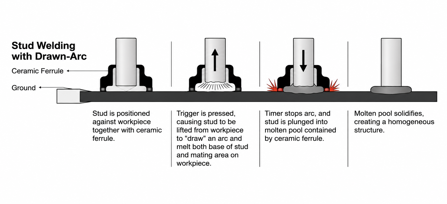
• When the ceramic ferrule absorbs moisture, the water content decomposes under high temperatures and generates hydrogen, causing hydrogen porosity.
• A mismatch between the ceramic ferrule and stud diameter, with excessive or insufficient clearance, will affect the protection performance of the weld pool.
• Excessive reuse of ceramic ferrules may cause inner wall damage or contamination, resulting in loss of protective function.
Solutions:
• Before use, ceramic ferrules should be dried in an oven at 150℃ for 2 hours to remove moisture.
• Ensure the ceramic ferrule matches the stud diameter, with the clearance controlled between 0.2–0.5 mm.
• Each ceramic ferrule should only be used once and must not be reused (ceramic ferrules are single-use consumables).
• Selecting high-quality ceramic ferrules with arc deviation prevention features can reduce the occurrence of porosity.
2.4 Environmental Factors — Excessive Humidity or Airflow Disturbance
High humidity in the welding environment or strong airflow around the welding area is a hidden factor contributing to porosity formation.
• When environmental humidity exceeds 70%, excessive water vapor exists in the air. Under the high temperature of the arc, moisture decomposes into H₂ and O₂. The hydrogen enters the weld pool and forms hydrogen porosity.
• Hydrogen pores usually appear as round or needle-shaped defects distributed inside the weld.
• Strong airflow in the welding area (such as from fans, air-conditioning outlets, or workshop drafts) can disturb the protective atmosphere and cause air to enter the weld pool.
Solutions:
• Workshop humidity should preferably be controlled between 40%–60%. When humidity exceeds 70%, welding speed should be reduced or dehumidification measures should be implemented.
• Install wind barriers around the welding area and control airflow speed below 0.5 m/s.
• When necessary, local shielding gas protection (such as Ar or CO₂) can be applied around the stud welding area. However, gas flow must be properly controlled (5–10 L/min recommended). Excessive flow may cause turbulence and introduce additional air into the weld pool.
2.5 Improper Welding Speed and Operating Technique
Excessive welding speed or improper operating techniques can increase the occurrence of porosity and slag inclusion.
• During continuous welding, excessive welding speed results in insufficient heat accumulation in the workpiece. The weld pool cools too quickly, preventing gases from escaping in time.
• If the welding gun is not perpendicular to the workpiece, the weld pool becomes unevenly distributed, resulting in inconsistent protection and increased risk of porosity on one side.
• If the welding gun is not pressed into the correct position, the anti-spatter sleeve cannot properly contact the workpiece, causing the weld pool to be exposed to air.
Solutions:
• For semi-automatic welding guns, the welding speed should be controlled at 20–25 studs per minute. For manual welding guns, the recommended speed is 15–20 studs per minute.
• The perpendicularity deviation between the welding gun and workpiece should be controlled within ±1°. Laser positioning equipment can be used for calibration.
• During welding, ensure the welding gun is properly pressed into position and that the anti-spatter sleeve maintains contact with the workpiece surface.
• After welding is completed, wait briefly before removing the welding gun to allow the weld pool to fully solidify and prevent pore formation caused by premature gun removal.
2.6Base Material and Stud Material Compatibility Issues
A mismatch between the base material and stud material, or excessive impurities in the base material, can easily result in porosity and slag inclusion.
High sulfur and phosphorus content in the base material can generate low-melting-point slag inclusions.
Insufficient deoxidizing elements such as Si and Mn in high-strength steel can result in poor weld pool deoxidation and the formation of CO porosity.
Internal porosity in die-cast aluminum components may be released under heat during welding, causing porosity in the weld.
Preventive Measures:
Ensure metallurgical compatibility between the base material and stud. Welding Procedure Qualification (WPQ) should be conducted when there is a significant material difference.
For high-strength steel applications, select studs with suitable Si and Mn content.
For cast aluminum components, perform X-ray / CT inspection before welding. If internal porosity exceeds the allowable limit, preheat at 150–200℃ before welding.
3. Defect Inspection and Validation Methods
Visual Inspection
Inspect the weld surface using the naked eye or a 5× magnifying glass.
Circular depressions indicate porosity, while irregular black or gray spots indicate slag inclusion. This method enables rapid screening of visible surface defects.
Bend Destructive Sampling Test
Bend the stud 15° in multiple directions and inspect the weld root.
Cracks, fractures, or detachment at the weld root indicate an unacceptable result. This method is commonly used for batch quality verification.
Equipment-Based Welding Energy Monitoring
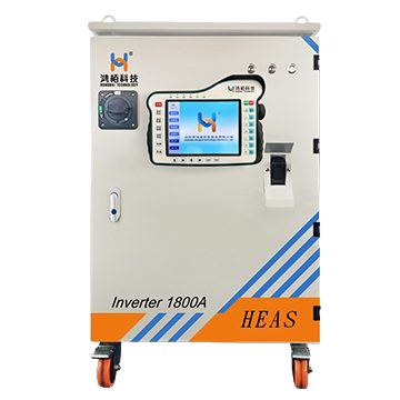
Modern stud welding systems (such as Hongbai Technology’s self-developed HEAS series and PIDS series) are equipped with welding energy monitoring functions.
When the actual welding energy falls below the preset lower limit, the system identifies a potential risk of incomplete fusion or porosity and triggers an alarm.
Ultrasonic Testing (UT)
For hidden internal weld defects, ultrasonic testing can be used to identify porosity and slag inclusion defects with a minimum equivalent size of 0.5 mm, enabling accurate evaluation of internal weld quality.
AI Intelligent Vision Inspection
Using YOLOv8-based vision algorithms for online inspection, the system can automatically identify defects such as porosity, slag inclusion, and arc deviation.
With detection accuracy ≥95% and inspection speed ≥50 parts/min, it is suitable for 100% inspection in mass production environments.
4. Summary (Final Version — Precise and Concise)
Porosity and slag inclusion defects require systematic control from six key aspects:
- Surface preparation at the source
- Welding parameter optimization
- Proper ceramic ferrule usage
- Production environment control
- Standardized operating procedures
- Base material and stud material compatibility
On-site improvement should follow a closed-loop process of:
cleaning first → parameter optimization → validation afterward.
Welding parameters, equipment status, and environmental data should be recorded for each production batch to establish a traceable quality management system.
For production lines, priority should be given to addressing the two most common causes: insufficient surface cleaning and excessive environmental humidity.
These improvements can rapidly and significantly reduce the defect rate of porosity and slag inclusion.
Hongbai Stud Welding Quality Control Solutions
To meet the requirements of automotive Body-in-White, automotive components, and new energy vehicle manufacturing for high stability and consistent welding quality, Hongbai Technology provides intelligent stud welding solutions.
Through high-precision digital welding control, real-time welding energy monitoring, weld quality data traceability, and intelligent process management, Hongbai solutions enable stable and reliable stud welding processes.
Hongbai HEAS series and PIDS series intelligent stud welding systems are widely applied in automotive manufacturing.
They help customers reduce welding defect rates, improve production efficiency, and establish a more reliable intelligent manufacturing quality management system.
Follow our LinkedIn account for more stud welding technology and defect optimization solutions.👇👇