
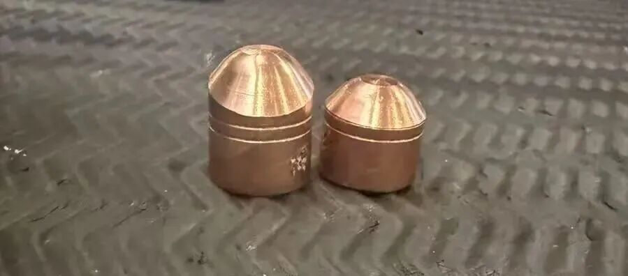
In automotive body-in-white (BIW) production, resistance spot welding electrodes are subjected to repeated pressure, heat, and material transfer. Regular electrode tip dressing is essential to restore the required weld face geometry and maintain consistent welding conditions.
However, a common problem on production lines is that the upper and lower electrode caps have different protruding lengths after dressing. One electrode appears higher than the other, even though both electrodes have been processed by the same dressing unit.
Why does this happen when the dressing unit is designed to dress both electrodes simultaneously?
The key is to distinguish between initial electrode length differences, unequal material removal, and electrode alignment errors. Identifying the actual cause helps maintenance engineers correct the problem without unnecessary parameter changes or repeated production interruptions.
Hongbai Technology provides electrode cap dressing equipment and AI vision inspection solutions for automotive welding applications, supporting more consistent electrode maintenance and quality inspection.
1. Understanding the Causes of Uneven Electrode Cap Projection
During resistance spot welding, electrode caps gradually wear and their weld faces may become enlarged, deformed, or contaminated. Electrode tip dressing removes excess material and restores the required weld face geometry.
In a properly configured dressing system, the upper and lower electrodes are processed according to the equipment’s design and the specified dressing parameters.
However, simultaneous dressing does not necessarily mean that both electrode caps will have identical final projection lengths.
The final result depends on three main factors:
- Initial projection: The upper and lower electrode caps may already have different protruding lengths before dressing.
- Material removal: The amount of material removed from each electrode may differ.
- Mechanical alignment: Electrode misalignment or an incorrect dressing position may affect the cutting process and the resulting geometry.
To investigate the problem, measure both electrodes before and after dressing. This helps determine whether the length difference existed before the dressing cycle or developed during the process.
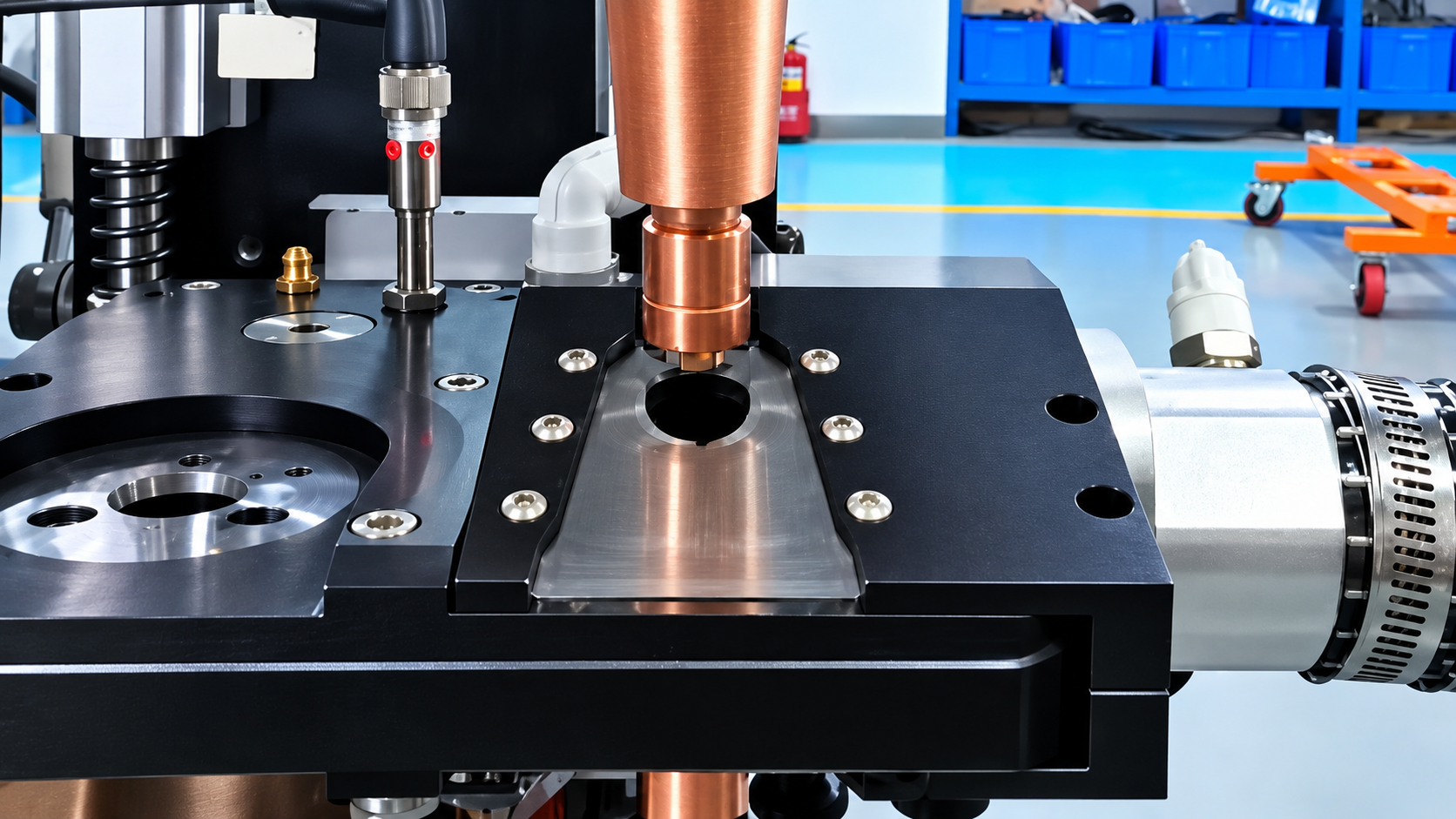
Electrode cap dressing restores the working face geometry and helps maintain consistent welding conditions.
2. Five Common Causes of Uneven Electrode Cap Lengths
2.1 Incorrect Electrode Cap Installation or Different Initial Dimensions
The first step is to verify the condition of the electrodes before dressing.
Different electrode cap dimensions, inconsistent seating depth, or incorrect installation can create a projection difference before the dressing cycle begins. Differences in electrode holder position or welding gun geometry may also contribute.
Recommended checks:
- Verify that the upper and lower electrode caps have the correct specifications.
- Check that both caps are fully seated and securely installed.
- Measure the initial electrode cap projection using the same reference point.
- Compare the measurements before and after dressing.
If the difference is already present before dressing, investigate the installation and electrode assembly rather than simply increasing dressing time.
2.2 Worn or Damaged Dressing Cutters
The dressing cutter directly affects the resulting weld face geometry.
Worn cutting edges, damaged blades, loose fasteners, or an incorrectly matched cutter can cause uneven cutting, incomplete dressing, or irregular electrode faces.
Cutter compatibility is particularly important when the upper and lower electrodes have different geometries. A standard cutter assembly designed for matching electrode caps may not be suitable for every special configuration.
Hongbai’s electrode cap dressing solutions can be configured with different cutter options according to the applicable electrode geometry and process requirements.
Recommended checks:
- Inspect the cutter edges for wear, chipping, and damage.
- Verify compatibility between the cutter and electrode cap geometry.
- Check the cutter mounting and fastening.
- Inspect the dressed faces for eccentricity, uneven cutting, or incomplete dressing.
Cutter wear should not automatically be identified as the cause of a projection difference. Measurements and face inspection are needed to confirm the diagnosis.
2.3 Electrode Misalignment and Incorrect Dressing Position
Electrode alignment is critical to consistent tip dressing.
If the electrode axis is offset from the cutter’s rotational center, the cutting conditions may become uneven. This can result in an off-center weld face, incomplete material removal, or irregular face geometry.
A tilted electrode holder, incorrect welding gun position, or a displaced dressing unit may also affect dressing quality.
Recommended checks:
- Verify the electrode position relative to the dressing cutter.
- Check the alignment of the upper and lower electrode axes.
- Inspect the electrode holders for bending or excessive tilt.
- Confirm that the dressing unit is correctly positioned and securely mounted.
If the problem occurs on only a few robots, begin with the individual welding gun, electrode holders, and dressing station before changing parameters across the entire production line.
2.4 Malfunctioning Floating Mechanism or Unstable Drive Conditions
Some electrode dressing units incorporate a floating mechanism to accommodate changes in electrode position and maintain suitable contact with the cutter.
If the floating mechanism sticks, the pneumatic supply becomes unstable, or the drive system operates incorrectly, the contact conditions during dressing may change.
The inspection procedure depends on the equipment design. Pneumatic systems require checks of air pressure, cylinders, and floating mechanisms, while servo-driven systems require checks of drive status, positioning, and mechanical transmission.
Recommended checks:
- Inspect the floating mechanism for restricted movement.
- Verify air pressure and pneumatic stability where applicable.
- Check bearings, transmission components, and drive operation.
- Confirm that the dressing pressure and cycle settings meet the equipment specifications.
The objective is to identify the actual mechanical or control fault rather than assume that every projection difference is caused by insufficient dressing pressure.
2.5 Incorrect Dressing Parameters or Different Electrode Wear Conditions
Dressing time and material removal settings influence how much material is removed during each cycle.
Insufficient dressing may leave worn areas or contamination on the weld face. Excessive material removal, on the other hand, can shorten electrode service life.
The upper and lower electrodes may also enter the dressing cycle with different wear conditions, mushrooming, deformation, or copper pickup. These differences can affect the final result.
Recommended checks:
- Verify dressing time and material removal settings.
- Compare the initial wear conditions of the upper and lower electrodes.
- Inspect for copper pickup, surface irregularities, and incomplete dressing.
- Adjust one parameter at a time within the approved operating range and record the results.
The objective is not simply to make both electrodes look the same length. It is to restore the required weld face geometry while controlling electrode consumption.
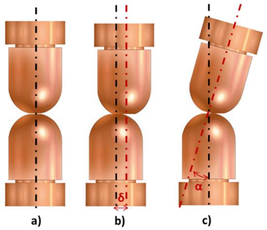
Cutter wear, electrode misalignment, and inconsistent dressing conditions should be checked when cap projections differ.
3. How Can Uneven Electrode Caps Affect Spot Welding Quality?
The effect of an electrode projection difference depends on the welding gun design, workpiece geometry, actual dimensional deviation, and the compensation available in the system.
When the difference exceeds the applicable process tolerance, potential consequences include:
Uneven electrode contact
One electrode may contact the workpiece earlier than the other, depending on the welding gun configuration and workpiece position.
Changes in the effective electrode force distribution
If the projection difference affects the contact condition or welding gun geometry, the actual force distribution may differ from the intended condition.
Inconsistent weld quality
Electrode face diameter, face geometry, alignment, and contact conditions influence resistance spot welding. If the projection difference is accompanied by electrode misalignment or irregular weld faces, process consistency may be affected.
Additional maintenance and downtime
If the electrode geometry falls outside the limits monitored by the welding system, additional inspections, alarms, or maintenance interventions may be required.
For automotive body-in-white production, maintaining consistent electrode geometry is an important part of welding process control. Acceptable limits should be established according to the welding gun design, equipment specifications, and validated process requirements.
4. A Practical Troubleshooting Procedure
Instead of repeatedly changing dressing parameters, maintenance teams can follow a structured inspection sequence.
| Step | Inspection | Objective |
|---|---|---|
| 1 | Measure upper and lower electrode projection before and after dressing | Identify when the difference develops |
| 2 | Verify electrode cap dimensions and installation | Eliminate initial dimensional differences |
| 3 | Inspect dressing cutters and mounting | Identify cutting-related problems |
| 4 | Check electrode alignment and dressing position | Detect mechanical positioning errors |
| 5 | Inspect the floating mechanism and drive system | Identify unstable movement or contact conditions |
| 6 | Review dressing parameters | Confirm appropriate process settings |
| 7 | Re-measure electrode geometry and validate weld quality | Verify the effectiveness of corrective action |
This procedure helps distinguish installation problems from dressing-related faults and reduces unnecessary trial-and-error adjustments.
5. How Hongbai Supports Electrode Dressing Quality Control
For automotive manufacturers, correcting a dressing defect is only part of the challenge. Maintaining repeatable dressing quality and identifying recurring defects are equally important.
Hongbai Technology develops electrode cap dressing equipment and AI vision inspection solutions for automotive welding applications. Depending on the selected configuration, dressing and inspection can be integrated into an electrode maintenance workflow.
AI Vision Inspection for Electrode Face Defects
Hongbai’s AI vision inspection solution is designed to identify 11 types of electrode cap face defects, helping operators detect conditions that may be difficult to assess consistently through manual visual inspection.
The inspection categories include:
- Black marks
- Protrusions
- Copper pickup
- Pits
- Radial marks
- Excessive face size
- Insufficient face size
- Irregular face geometry
- Eccentric electrode faces
- Flower-pattern marks
- Incomplete dressing
- Uneven dressing
These defect categories help production teams identify problems with electrode face condition and dressing quality.
Dual-Criteria NG Judgment
Hongbai’s AI inspection solution uses a dual-criteria judgment method based on the total NG defect area and the NG area ratio.
According to the configured inspection logic, both criteria are evaluated against their respective thresholds. This helps distinguish acceptable surface variations from defects that meet the configured NG conditions.
Inspection Statistics and Traceability
The system supports OK/NG statistics and inspection records, helping production teams review defect trends and investigate recurring dressing problems.
For automotive production lines operating multiple robotic welding guns, these records can provide useful information for maintenance planning and quality analysis.
It is important to distinguish between electrode face defect inspection and dimensional measurement. Detecting an irregular weld face does not automatically provide a direct measurement of the overall projection difference between the upper and lower electrodes.
If an application requires measurement of electrode cap projection, axis offset, or angular deviation, the relevant geometric measurement functions and their validated accuracy must be confirmed for the selected system configuration.
By combining appropriate dressing equipment, routine mechanical inspections, and suitable vision inspection methods, manufacturers can establish a more controlled and traceable electrode maintenance process.
Correct the Root Cause, Not Just the Symptom
Uneven electrode cap projection after dressing can result from incorrect installation, worn or mismatched cutters, electrode misalignment, mechanical instability, or unsuitable dressing parameters.
The most effective approach is to measure both electrodes before and after dressing, identify when the difference develops, and correct the corresponding cause.
For automotive manufacturers seeking more consistent electrode maintenance, Hongbai’s electrode cap dressing and AI vision inspection solutions offer options for improving dressing quality control and defect traceability.
Consistent electrode geometry starts with the right dressing process—and continues with reliable inspection.
Hongbai Technology