1. Why Is Grounding Important in Stud Welding?
A stud welding system requires a complete welding current circuit. Current flows from the power source through the welding cable and weld gun, then passes through the stud and workpiece before returning to the power source through the ground cable.
The impedance of every connection in this circuit can affect welding performance. However, the return path is often overlooked. Although the ground connection may appear to be a simple cable and clamp, its condition affects the current return path and, in systems with arc voltage monitoring, voltage measurement.
A common issue on the production floor is inconsistent weld quality despite unchanged welding parameters. The same power source may perform normally at one workstation but produce weak or incomplete welds at another. In such cases, the ground circuit should be checked alongside the welding parameters.
On Hongbai power sources, the welding ground connection and arc voltage sensing connection are provided through separate interfaces.
For example, on the SAW-3600R, item 13 on the I/O panel is the welding ground cable connection, while item 14 is the arc voltage sensing signal input. The SAW-3600A/B also have separate connections for the arc voltage sensing cable and welding ground cable on the rear panel.
The PIDS power source uses X6 for the ground cable and X7 for the arc voltage sensing cable. Connectors X1 to X5 correspond to its five welding channels.
These connections serve different functions and should not be treated as interchangeable.
Hongbai’s grounding configurations can be grouped into four common arrangements. The appropriate configuration depends mainly on three factors: the number of workstations, the number of power sources, and the number of welding terminals.
2. Configuration 1: Multiple Grounding Points at a Single Workstation
Arrangement: One workstation, one power source, and multiple grounding points.
The ground cables can be connected in series or in parallel. This is a basic configuration commonly used for single-machine manual or semi-automatic stud welding.
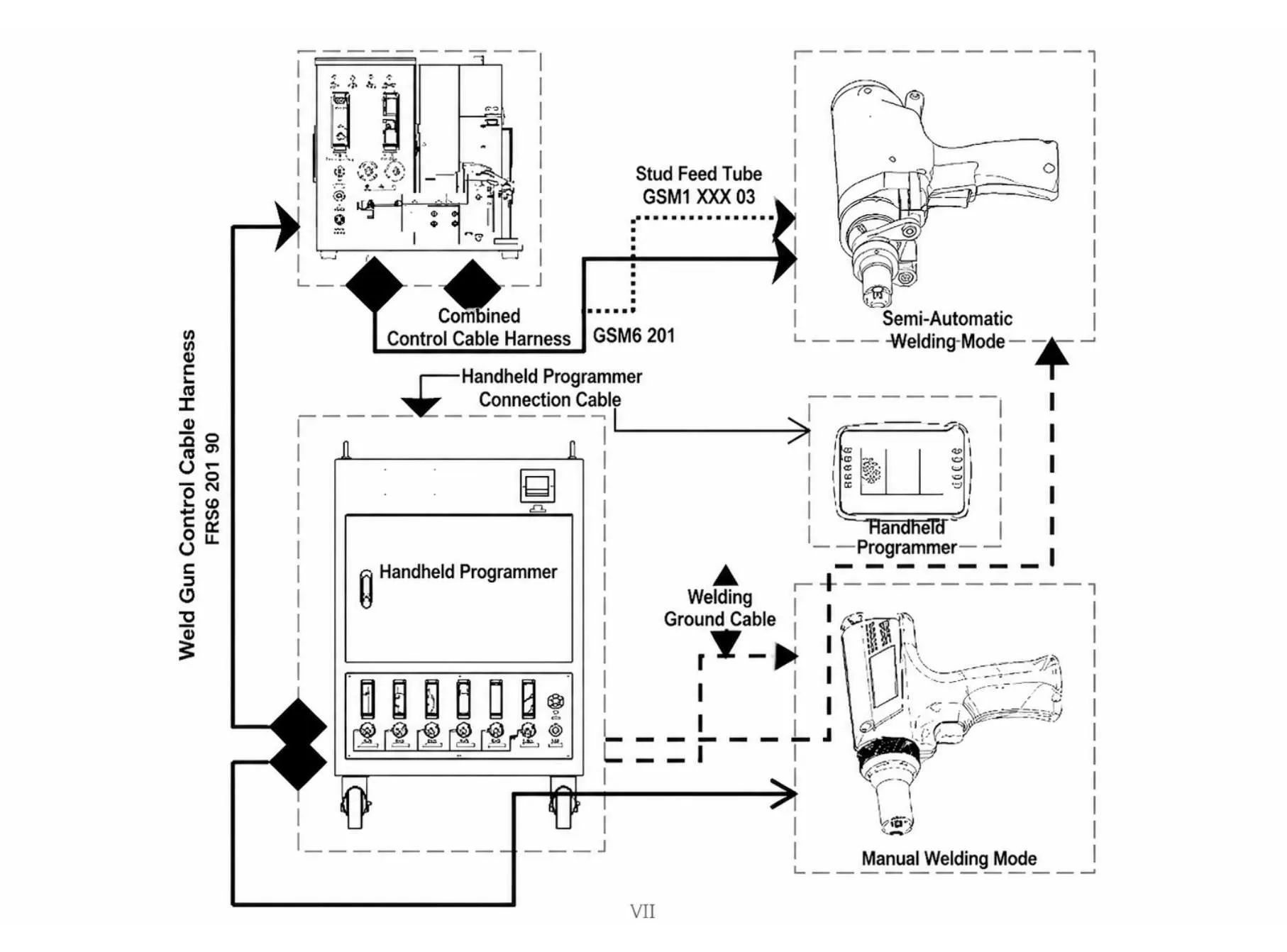
For example, a standard SAW-3600 setup with a GMM6 manual servo weld gun, or a GSM6 semi-automatic servo weld gun paired with an FRS6 stud feeder, falls into this category.
Why use multiple grounding points?
The workpiece surface is not always an ideal electrical contact surface. Oxidation, oil, rust-preventive films and coatings can affect contact quality. Multiple grounding points provide alternative current return paths and help reduce the impact of an unreliable individual connection.
In a series arrangement, multiple grounding points are connected one after another, with the final cable returning to the power source. This simplifies cable routing, but the condition of each intermediate connection can affect the overall circuit.
In a parallel arrangement, each grounding point has its own cable connected back to the designated ground connection. This requires more cabling, but provides more independent connection paths.
The choice should be based on the workpiece geometry, grounding point locations and cable routing requirements.
3. Configuration 2: Multiple Workstations Connected in Parallel
Arrangement: Multiple workstations share one power source, with the ground connections arranged in parallel.
When one power source serves several workstations, a parallel grounding arrangement is generally preferred. Each workstation has its own ground connection, which is then connected to the designated grounding point on the power source.
With a series arrangement, the condition of an upstream connection may affect the return path of downstream workstations, increasing the potential for interaction between stations.
A parallel arrangement helps reduce this interaction by providing more independent current return paths.
This configuration is suitable for multi-channel power sources. The Hongbai SAW-3600 series offers the following channel configurations:
- SAW-3600A: Five independent welding channels.
- SAW-3600B: Two to three welding channels.
- SAW-3600C: Two welding channels.
Depending on the system configuration, each channel can be connected to the same or different types of welding terminals. The channels operate independently or simultaneously according to the equipment’s control logic.
The multi-channel design allows one power source to support multiple welding stations.
4. Configuration 3: Two Power Sources at One Workstation with Multiple Grounding Points
Arrangement: Two power sources, one workstation and multiple grounding points.
This configuration is commonly found in robotic stud welding applications.
One important limitation must be observed:
A common busbar arrangement connecting multiple power sources is only applicable to steel stud welding.
For aluminum stud welding, this common busbar arrangement is not applicable.
Why might a robotic workstation require two power sources? For example, the same fixture may need to accommodate different stud specifications, or separate welding operations may be assigned to independent power sources.
The Hongbai SAW-3600R robotic stud welding system features five independent welding channels. Depending on the application, it can be connected to different welding terminals, including manual servo weld guns, semi-automatic servo weld guns and robotic servo weld guns.
5. Configuration 4: Multiple Welding Terminals at One Workstation with Multiple Grounding Points
Arrangement: One power source, one workstation, multiple welding terminals and multiple grounding points.
This configuration is also common in robotic welding systems.
The main difference from Configuration 3 is the relationship between the power sources and welding terminals. Configuration 3 involves multiple power sources, whereas Configuration 4 uses one power source connected to multiple welding terminals.
The Hongbai PIDS power source is a typical example. It features five independent welding channels and can be connected to different types of stud feeders and welding terminals. During operation, the power source serves each feeder in sequence according to the system control logic.
The HEAS series also features five independent welding channels and supports three types of welding terminals.
When multiple terminals share a grounding system, the condition of each connection contributes to the overall current return path. The number and location of grounding points should therefore be planned according to the number of welding channels, terminal layout and workpiece geometry.
6. Why Are Configurations 3 and 4 Common in Robotic Applications?
Both configurations involve multiple power sources or welding terminals sharing a workstation grounding system. They are therefore frequently used in robotic stud welding projects.
Robotic welding offers a high degree of positional repeatability. The gun path, welding positions and relationship between the robot and fixture are generally defined through programmed movements and coordinate systems.
This consistency makes it easier to plan the welding cable routes, grounding connections and terminal layout as part of the overall system design.
In manual applications, welding positions and operating conditions can vary more frequently. When several terminals share a grounding system, connection management and routine inspection also become more demanding.
For this reason, selecting either configuration requires consideration of more than the number of power sources and terminals. Workstation layout, robot movement range and production cycle time should also be evaluated.
7. Ground Cable and Voltage Sensing Cable Specifications
Ground cables and voltage sensing cables are two components that require particular attention during installation. Incorrect connections may not be visually obvious, but can affect the welding current circuit and measurement results.
Common Hongbai configurations include:
| Item | Specification |
|---|---|
| Standard ground cable | 5 m, 70 mm² |
| Standard sensing cable | 0.5 mm² |
| Optional ground cable | 95 mm² |
| Optional sensing cable | 2.5 mm² |
Hongbai’s accessory documentation also lists ground cable assembly part number Y001 928 0001B. The documented assembly length is 6.0 m and it includes welding output and arc voltage sensing cables. It is supplied as part of the welding system’s cable package.
The specified relationship between ground cable length and cross-sectional area is:
- L ≥ 6 m: S = 70 mm².
- L < 6 m: S = 50 mm².
The voltage sensing wire attached to the ground clamp has a cross-sectional area of 0.5 mm². The actual specification should be confirmed against the cable configuration for the relevant power source.
Why is the voltage sensing cable connected to the ground clamp?
Arc voltage is the potential difference between two measurement points. The power source needs a voltage reference close to the actual welding area, rather than simply relying on the voltage measured at its output terminals.
Welding cables have electrical resistance and therefore produce a voltage drop during welding. If the measurement point is located on the power source side, the measured voltage may include this cable voltage drop.
Connecting the sensing wire to the designated measurement point on the workpiece side helps reduce this effect and provides a measurement that more closely reflects the actual welding conditions.
The sensing cable is therefore not just an accessory. Its connection point and contact condition should follow the equipment manufacturer’s requirements.
8. What Should Be Confirmed Before Selecting a System?
Before selecting a stud welding system, four factors should be confirmed: workpiece material, number of workstations, power source configuration and welding terminal layout.
For robotic projects involving multiple power sources connected through a common busbar, or multiple terminals sharing a grounding system, the connection method and its applicable limitations should be confirmed during the equipment design stage. This helps avoid changes to the current return connections after installation.
For each application, the final grounding configuration and cable specifications should be determined based on the power source model, stud material and actual workstation layout.
Frequently asked questions
Why is grounding important in stud welding?
A stud welding system requires a complete welding current circuit. The ground connection affects the current return path and, in systems with arc voltage monitoring, voltage measurement.
What factors determine which grounding configuration to use?
The appropriate configuration depends mainly on the number of workstations, the number of power sources, and the number of welding terminals.
Are the welding ground connection and arc voltage sensing connection interchangeable?
No. On Hongbai power sources they are provided through separate interfaces and should not be treated as interchangeable. For example, on the SAW-3600R, item 13 is the welding ground cable connection and item 14 is the arc voltage sensing signal input.
Why use multiple grounding points at a single workstation?
Workpiece surfaces are not always ideal electrical contact surfaces. Oxidation, oil, rust-preventive films, and coatings can affect contact quality, so multiple grounding points provide alternative current return paths.
What is the difference between series and parallel grounding arrangements?
In a series arrangement, multiple grounding points are connected one after another, with the final cable returning to the power source. In a parallel arrangement, each grounding point has its own cable connected back to the designated ground connection.