
2026-08-11
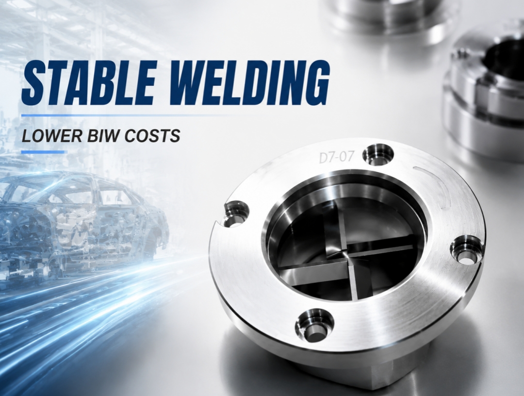
In the demanding environment of automotive Body-in-White (BIW) welding, electrode cap dressing blades may appear small, but they play a critical role in determining weld spot quality, electrode cap service life, and overall production cost. Behind a seemingly simple blade lies a complete chain of engineering expertise, including material science, precision manufacturing, and strict quality management. With decades of experience in welding equipment development, Shenzhen Hongbai Technology Co., Ltd. has successfully transformed its independently developed electrode cap dressing blades from ordinary consumable components into precision-engineered products integrating advanced structural design, high-accuracy manufacturing processes, and international certification standards. 1. Design Philosophy: A Fundamental Shift from “Cutting” to “Dressing” Traditional electrode cap dressing is essentially a cutting process, where sharp cutting edges forcibly remove the copper-aluminum alloy layer accumulated on the electrode cap surface. Although this method is straightforward, it has two major limitations: High material removal rate (approximately 0.08 mm per dressing cycle) Short blade service life (only around 8,000–12,000 dressing cycles for single-edge blades) Hongbai’s dressing blade design achieves a breakthrough by redefining the fundamental dressing principle. 1.1 Multi-Edge Structure: From Single Cutting to Multi-Stage Dressing The core innovation of Hongbai dressing blades lies in the multi-edge structure. Currently, Hongbai provides four blade configurations. Taking the four-edge blade as an example, its four cutting edges are arranged at 90-degree intervals. During the dressing process, multiple edges work simultaneously, distributing cutting forces across several contact points. This reduces the material removal amount per dressing cycle to only 0.01–0.035 mm, bringing the process closer to precision dressing rather than conventional cutting. The direct benefits include: Reduced electrode cap material consumption Extended electrode cap service life Increased welding capacity from approximately 3,000 weld spots to 6,000 weld spots per pair of electrode caps 1.2 Four-Edge Right-Angle Design: 90° Geometry and 0.01 mm Dressing…
2026-08-10
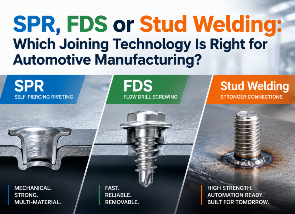
Introduction: The Evolution of Joining Technology in Modern Manufacturing For decades, resistance spot welding and traditional welding processes have been widely used in automotive manufacturing and industrial production. However, the rapid development of electric vehicles (EVs), lightweight structures, and multi-material applications has created new challenges for joining technologies. Modern manufacturing is no longer limited to single-material structures. Increasingly, manufacturers are working with combinations of: High-strength steel (AHSS) Aluminum alloys Galvanized steel Composite materials Multi-layer structures These materials provide significant advantages in weight reduction, energy efficiency, and product performance. However, they also introduce new challenges, including: Material compatibility issues Welding deformation Porosity and cracking risks Difficult access in complex structures Higher requirements for automation and quality monitoring For example, aluminum alloys have high thermal conductivity and a stable oxide layer on the surface, making traditional fusion welding more challenging. Problems such as unstable arc initiation, heat distortion, and welding defects can affect connection reliability. In addition, joining dissimilar materials such as steel and aluminum remains difficult due to differences in melting temperature, thermal expansion, and metallurgical properties. As a result, advanced joining technologies such as Stud Welding, SPR (Self-Piercing Riveting), and FDS (Flow Drill Screwing) have become increasingly important solutions for modern manufacturing. These technologies are not replacements for each other. Instead, each technology provides unique advantages for different material combinations, structural designs, and application requirements. 1. Stud Welding: A Reliable Solution for Functional Fastening Stud welding is a process that permanently joins a metal stud to a workpiece through an arc welding process. During welding, an arc is generated between the stud and the base material. After the contact surface melts, pressure is applied to complete the weld, creating a strong metallurgical connection. Unlike traditional welding methods that mainly join metal components together, stud welding creates an integrated fastening point…
2026-08-06
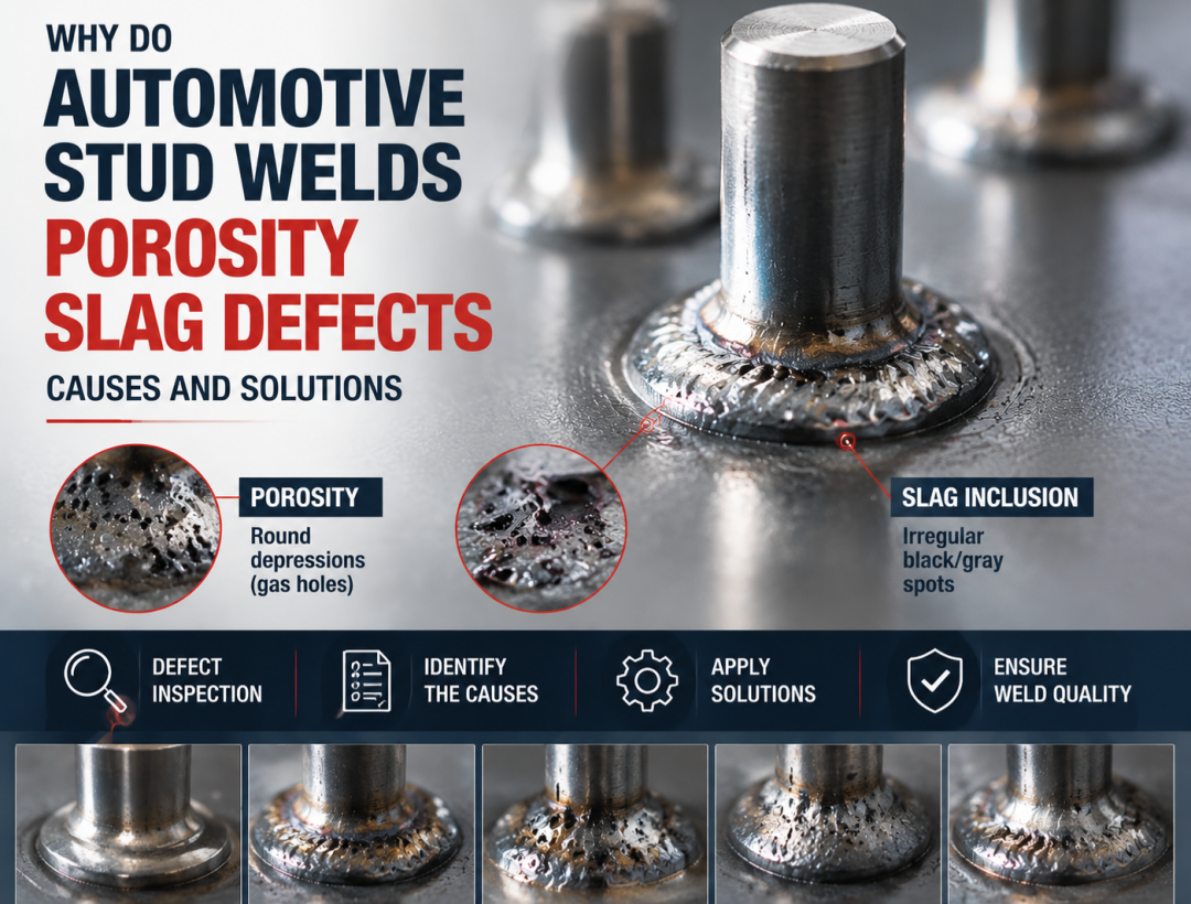
Introduction In automotive Body-in-White (BIW), automotive components, and new energy vehicle structural manufacturing, stud welding is widely used for applications such as cable harness fixing, heat shield installation, interior component mounting, and structural part assembly. However, in actual production, issues such as poor weld integrity, porosity, slag inclusion, and incomplete fusion remain key factors affecting stud welding quality stability. In severe cases, these defects can reduce stud strength and even cause stud detachment, affecting downstream assembly processes and product reliability. Based on stud welding principles and practical industrial applications, this article systematically analyzes the formation mechanisms, major causes, and engineering solutions for porosity and slag inclusion defects. 1. Formation Mechanism of Porosity and Slag Inclusion 1.1 Porosity Formation Mechanism: During the stud welding process, the high-temperature arc rapidly melts the welding area and forms a weld pool. If gases (such as H₂, CO, and N₂) inside the weld pool cannot escape before the molten metal solidifies, they will remain trapped inside the weld and form porosity. Porosity is mainly classified into: Surface porosity Internal porosity Among them, internal porosity is more difficult to detect and can reduce the effective strength of the welded joint. 1.2 Slag Inclusion Formation Mechanism: Slag inclusion refers to non-metallic impurities generated during the welding process that fail to escape in time and remain trapped inside the weld after solidification, forming defects. The main sources include: Oxides on the base material surface Oil contamination and foreign materials Coating residues Oxidation products generated during the welding process Slag inclusion reduces the effective bonding area of the weld and creates stress concentration areas, affecting weld joint reliability. 2. Six Root Causes of Porosity and Slag Inclusion 2.1 Workpiece Surface Contamination — The Most Common Cause Insufficient cleaning before welding is the primary cause of porosity and slag inclusion….
2026-07-21
Although defects such as weld nugget deviation and cold welds/incomplete fusion cannot be completely eliminated, their occurrence can be reduced to an extremely low level through systematic process control, real-time quality monitoring, and regular equipment maintenance. The following solutions focus on two critical defect areas — weld nugget deviation and cold welding/incomplete fusion — combining proven process optimization methods with advanced intelligent welding technologies. 1. Precise Control of Weld Nugget Deviation Weld nugget deviation is mainly caused by arc blow (magnetic arc deflection) and uneven heat dissipation conditions. 1.1 Eliminating Arc Blow — Prevention at the Source Symmetrical grounding (core measure) The ground connections should be positioned symmetrically on both sides of the welding location. This prevents uneven electromagnetic fields from deflecting the arc and is the most effective method for eliminating arc blow. Remove or ground nearby metal masses If large metal components, reinforcement plates, or conductive structures are located close to one side of the weld area, they should be removed or properly grounded to avoid magnetic field interference. Rotate the welding torch For manual stud welding, if arc deflection occurs toward one direction, rotating the torch handle by 90° can change the magnetic field distribution and improve arc stability. Control lift height Excessive lift height or missing ceramic ferrules can increase arc instability. Recommended lift height: General range: 1.0–1.6 mm Always use ceramic ferrules whenever possible to stabilize the arc. Figure: Symmetrical Grounding Configuration for Arc Blow Prevention Proper grounding layout plays a critical role in stabilizing the welding arc. Symmetrical grounding reduces magnetic field imbalance and prevents arc deflection, helping maintain consistent weld nugget positioning. 1.2 Optimizing Heat Distribution for Different Materials and Thicknesses Apply high-energy welding parameters Using a high current and short welding time (strong welding schedule) increases current density and reduces the influence…
2026-07-16
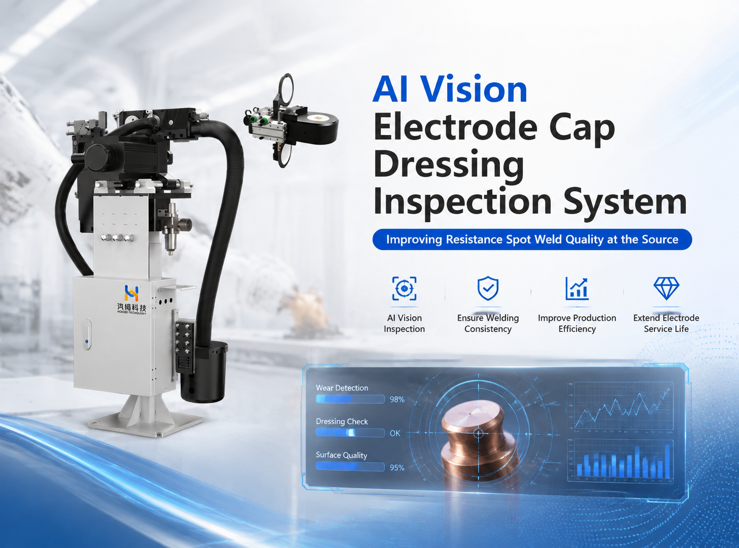
In automotive Body-in-White (BIW) production, resistance spot weld quality has a direct impact on vehicle structural integrity, safety, and durability. When investigating weld defects, manufacturers often focus on welding current, electrode force, and weld time. However, one critical factor affecting weld consistency is frequently overlooked—the condition of the electrode cap. Field experience has shown that inconsistent electrode cap dressing quality is one of the major causes of expulsion, undersized weld nuggets, weak welds, and poor weld consistency. As smart manufacturing continues to evolve, traditional maintenance methods based on manual inspection or fixed dressing intervals can no longer meet the requirements of high-speed automated production. AI-powered machine vision is rapidly becoming a new standard for resistance spot welding quality control. Why Is Electrode Cap Dressing So Important? The electrode cap directly influences current distribution and the electrical contact condition during resistance spot welding. After dressing, defects such as: • Off-center electrode face • Out-of-round electrode face • Copper pickup • Pits or raised surfaces • Incomplete or uneven dressing may result in: • Uneven current density • Inconsistent weld nugget size • Increased weld expulsion • Reduced weld strength • Shortened electrode life Therefore, electrode cap dressing quality affects not only electrode service life, but also the stability and consistency of every weld. Challenges with Conventional Electrode Dressing Many welding lines still rely on traditional electrode maintenance methods, including: • Dressing after a fixed number of welds • Manual visual inspection • Scheduled electrode cap replacement These methods present several limitations: • Inspection results depend heavily on operator experience. • Small surface defects are difficult to detect. • Premature dressing increases consumable costs, while delayed dressing compromises weld quality. • Lack of digital records makes root cause analysis and quality traceability difficult. For today’s high-volume automated welding lines, these approaches are…
2026-06-24
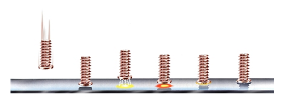
In automotive manufacturing, home appliance production, and precision equipment assembly, stud welding has become an indispensable joining process, valued for its high efficiency, reliability, and minimal thermal impact on the base material. Among its variants, short-cycle drawn-arc stud welding (SC) stands out for its rapid welding speed, precise heat input, and adaptability to thin-sheet and coated materials, making it a cornerstone technology in body-in-white (BIW) fabrication and subassembly production. Yet, maintaining consistent weld quality remains a persistent challenge. Defects such as spatter, cold welds (lack of fusion), porosity, and burn-through not only impair surface appearance but can also lead to functional failures. This article, grounded in the technical principles of leading systems—including those from Hongbai Technology and Emhart—provides an in-depth analysis of the process adjustment techniques for short-cycle drawn-arc stud welding. It is intended to offer a systematic, shop-floor-ready quality assurance framework for welding engineers and field technicians. 1. Process Principle and Core Parameters of Short‑Cycle Drawn‑Arc Stud Welding 1.1 Operating Principle and Sequence Control Short‑cycle drawn‑arc welding differs fundamentally from long‑cycle or capacitor‑discharge stud welding. Its essence lies in the precise timing of a highly controlled sequence to achieve a sound joint within an extremely short weld cycle. The standard sequence comprises the following phases: Contact Phase (Stud on Workpiece – SOW): The stud tip contacts the workpiece perpendicularly, closing the welding circuit. The system detects the SOW signal to initiate the cycle. Pilot Arc Phase: A low pilot current (typically ≈30 A) is applied while the linear motor (LM) rapidly lifts the stud to a preset height, striking a stable arc. This step removes surface contaminants (oil, oxides) to ensure stable main‑arc ignition. Main Arc Phase: Upon successful pilot arc establishment, the system instantly switches to the main welding current—ranging from several hundred to over a thousand amperes. The high‑energy arc rapidly melts…
2026-06-08
As an efficient and stable solid-phase metal joining process, short-cycle drawn arc stud welding has been widely applied in industrial fields including automobile manufacturing, marine engineering and household appliance production due to its outstanding welding efficiency and joint reliability. The welding forming quality and joint mechanical properties of the process are highly dependent on the accurate matching and coordinated regulation of process parameters. Based on the technical specifications of multiple brands of stud welding equipment and combined with on-site commissioning experience, this paper systematically constructs a standardized and implementable process commissioning methodology from four dimensions: process parameter system, standardized commissioning procedure, process window optimization, and root cause analysis of defects and faults. It provides technical support for engineering technicians to quickly calibrate the optimal welding process window and improve welding process consistency and product yield. 1. Process Parameter System and Physical Significance The electrical welding process of short-cycle drawn arc stud welding can be divided into four core stages: short-circuit stage, pilot arc striking stage, main arc welding stage and forging forming stage. Each welding stage is equipped with exclusive corresponding process parameters. These parameters are not independent of each other but have strong coupling correlations, which jointly determine the welding heat input and weld pool forming state, and ultimately directly affect the forming quality and comprehensive mechanical properties of welding joints. Combined with the official technical manuals and process specifications of mainstream equipment brands such as Hongbai SAW-3600 series, PIDS series and Tucker, this paper systematically sorts out and summarizes the core parameter system of short-cycle drawn arc stud welding, as shown in the table below. Parameter Group Parameter Name Physical Significance / Functional Effect Typical Range Commissioning Priority Arc Striking Parameters Pilot Current Generates a stable low-current arc to remove oil contamination and galvanized layers on the workpiece…
2026-05-22
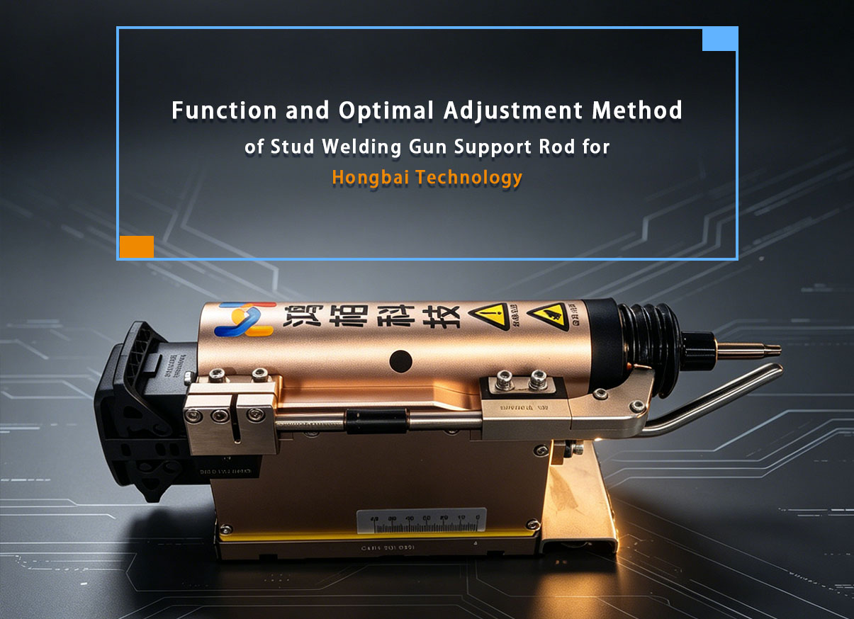
The support leg (or standoff leg) is a critical component on a stud welding gun, particularly on automatic welding guns. Below is a detailed explanation of its function and the best method for adjustment: I. Functions of the Support Leg The support leg (also referred to in some documentation as the foot assembly or front support leg) has the following primary functions: 1. Positioning the Stud Plunge/Protrusion: The support leg is used to determine the protruding length of the stud end relative to the front face of the welding gun (i.e., the stud plunge/protrusion length). This is a critical parameter affecting weld quality. 2. Ensuring Stud Alignment: The support leg works in conjunction with the chuck and the ferrule (or ceramic arc shield) to ensure the stud is centered in the welding gun, preventing welding defects caused by misalignment or off-center positioning. 3. Stabilizing the Welding Position: During the welding process, the support leg contacts the workpiece surface, ensuring a fixed relative position between the welding gun and the workpiece, thereby preventing gun movement or instability during welding. 4. Protecting the Contact Tip: The support leg is designed such that the end face of the contact tip is recessed approximately 2 mm below the end face of the support leg, effectively protecting the contact tip from damage caused by contact with the workpiece. II. Best Method for Adjusting the Support Leg Step 1: Verify Basic Conditions • The gun piston rod is naturally extended forward under compressed air pressure. • A stud is loaded into the contact tip. • The stud is in its final welding position within the contact tip. Step 2: Adjust the Support Leg Position Core Principle: The support leg must be positioned between the chuck and the stud. It must not be located behind…
2026-04-16
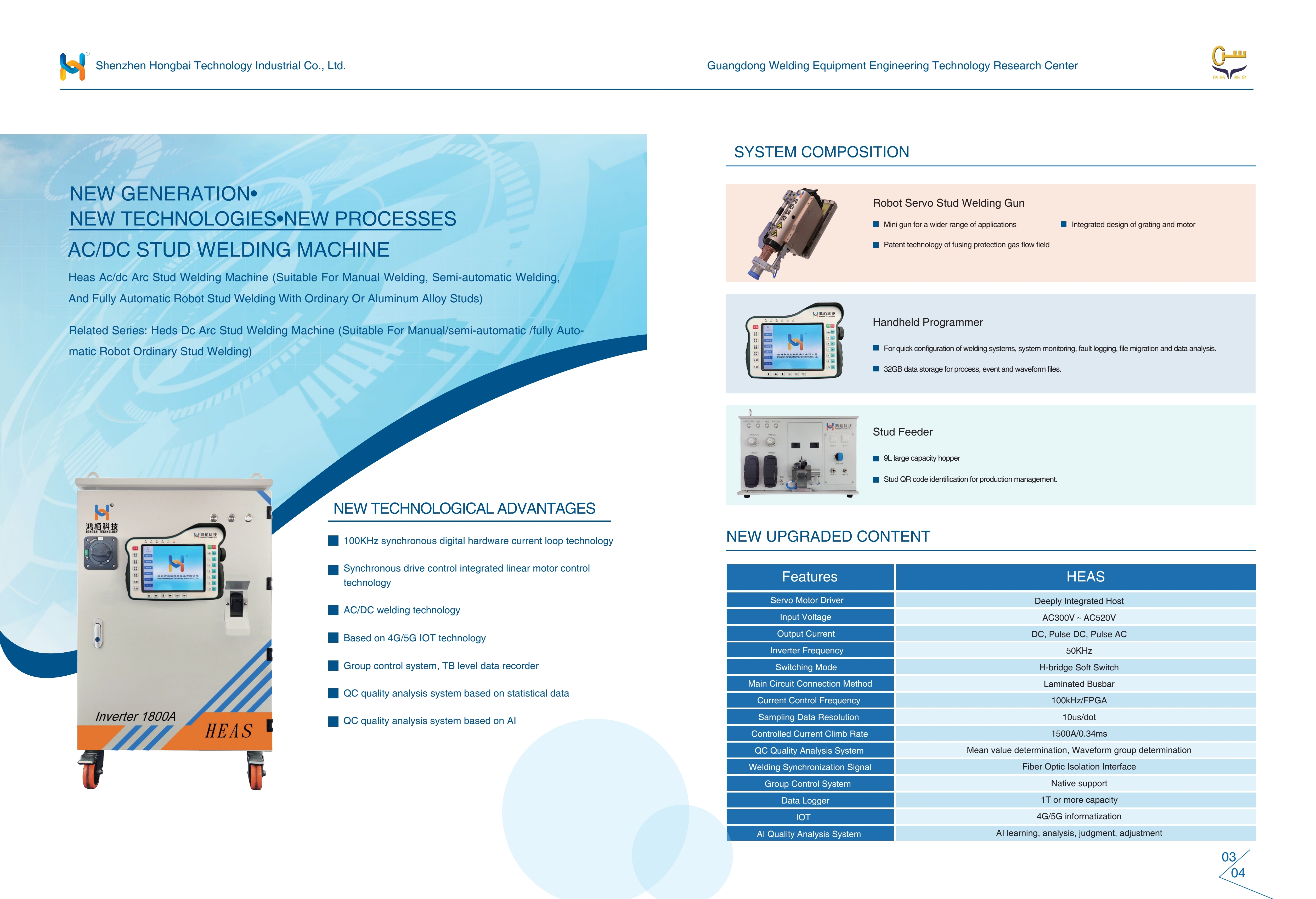
Industry Background: The Challenge of Aluminum in Automotive Manufacturing As the automotive industry accelerates toward lightweighting and electrification, aluminum body structures have become the mainstream solution for modern vehicle design. However, this shift introduces significant challenges for traditional joining technologies—especially in stud welding. Aluminum’s high thermal conductivity, rapid oxidation, and unique metallurgical behavior create what engineers often call an “impossible triangle”: achieving high quality, high efficiency, and high stability simultaneously. Conventional DC drawn arc stud welding systems struggle to meet these demands, particularly in Body-in-White (BIW) applications. HEAS Solution: A New Generation of AC/DC Stud Welding Technology To address these challenges, Hongbai Technology has developed the HEAS AC/DC Stud Welding System, a 5th-generation fully digital intelligent solution designed specifically for demanding aluminum welding applications. 1. Multi-Dimensional Energy Control Unlike traditional DC systems, HEAS supports both DC and programmable AC welding modes. Active cathodic cleaning effect efficiently removes oxide layers on aluminum surfaces Adjustable waveform and frequency optimize arc behavior Programmable polarity switching enables better heat distribution This allows precise control of welding energy—not just in magnitude, but also in timing and direction. 2. Intelligent Closed-Loop Process Control HEAS integrates a high-speed control architecture: 100kHz digital current loop for ultra-fast response High-frequency servo motor control for precise lift motion Dynamic arc voltage monitoring and compensation This ensures real-time adjustment of welding parameters, significantly improving process stability and consistency—even under variable conditions. 3. Full Data Traceability & AI Quality Analysis Traditional quality control relies on post-weld inspection. HEAS transforms this into a data-driven process: Full recording of current, voltage, and displacement waveforms Advanced waveform-based quality evaluation AI-driven defect prediction and process optimization Every weld becomes traceable, measurable, and continuously improvable. 4. Designed for Industry 4.0 Integration HEAS is not just a welding machine—it is a smart manufacturing node. Seamless integration with robots…
2026-03-09
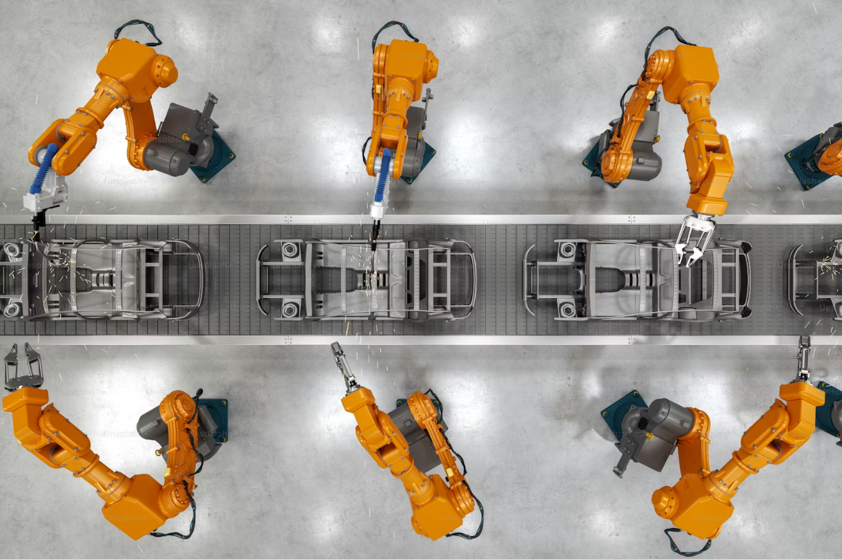
Short-cycle stud welding is widely adopted in thin sheet joining scenarios such as automotive components and home appliance enclosures due to its high welding speed and low heat input. However, when welding 0.7mm thin galvanized sheets, cold welding defects of studs—characterized by incomplete weld fusion and insufficient bonding strength—are prone to occur. These defects not only compromise structural integrity but may also lead to subsequent assembly loosening and seal failure. Combining the characteristics of galvanized sheets and the process principle of short-cycle welding, this paper analyzes the causes of cold welding and proposes targeted solutions for the automotive manufacturing industry. I. Core Causes of Cold Welding: Galvanized Coating Interference & Heat Input Imbalance Short-cycle stud welding achieves metallurgical bonding between studs and base metals through instantaneous arc heating, rapid cooling, and precise heat input control. Yet the properties of the galvanized coating on 0.7mm sheets (melting point at 419℃, boiling point at 907℃, far lower than steel’s 1538℃) and the high thermal conductivity of thin sheets undermine welding stability in two key aspects: 1.Galvanized coating heat absorption and volatilization interference: Under arc heating, the galvanized coating melts and volatilizes prior to the steel sheet, generating zinc vapor. Without proper coating removal or parameter setting, zinc vapor blocks direct contact between the arc and steel sheet, leading to insufficient molten pool temperature and incomplete fusion—i.e., cold welding. Meanwhile, zinc vapor is likely to cause spatter, damaging molten pool continuity. 2.Heat input imbalance: The high thermal conductivity of 0.7mm thin sheets means excessive welding current or extended welding time can easily cause burn-through, while insufficient current or overly short time results in inadequate melting of studs and steel sheets, failing to form an effective fusion layer. Both scenarios trigger cold welding. II. Systematic Solutions: Precise Control of Pretreatment, Parameters and Processes To…
2026-02-26
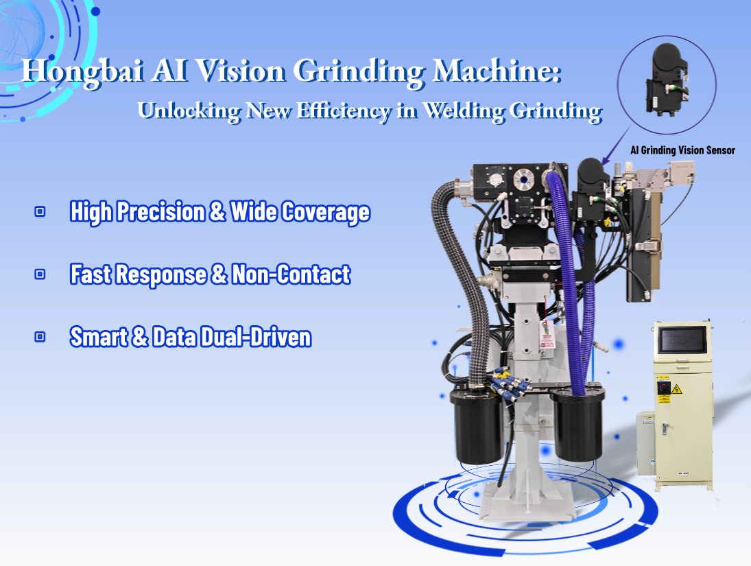
AI Vision Empowers Spot Welding Quality for BIW E‑series Electrode Cap Dress Inspection System by Hongbai Tech In modern intelligent manufacturing, especially on automotive Body-in-White (BIW) welding production lines, resistance spot welding is widely used as an efficient and reliable joining process for high-strength steel, aluminum alloy and other materials. Its welding quality directly determines the safety, durability and structural strength of the entire vehicle. Among the key factors influencing spot welding quality, electrode cap dressing quality is often underestimated yet critical. It determines current conduction efficiency, contact stability, weld nugget size, spatter control and electrode service life. With the deep integration of Industry 4.0 and artificial intelligence, traditional maintenance methods relying on manual visual inspection or fixed-interval replacement can no longer meet the requirements of high-cycle, high-quality and intelligent production. In response, Shenzhen Hongbai Technology Industrial Co., Ltd. has launched the E-series AI Vision Electrode Cap Dress Inspection Sensor System. With high-precision imaging, real-time defect identification and closed-loop feedback, it has become core equipment to ensure the stability of spot welding processes. This paper analyzes the importance of electrode cap dressing, the principles and functions of the AI vision inspection system, and explains how it improves the consistency and reliability of spot welding nuggets by enhancing dressing quality. https://www.hongbaiweld.com/all-product/robot-series/daytime-running-lights2677.html Core Influence of Electrode Cap Dressing Quality on Spot Welding Performance As the key medium for current transmission, the end-face condition of the electrode cap directly affects the physical behavior of welding: Contact Area and Current Density: Pits, copper adhesion, eccentricity and other defects lead to abnormal current density, resulting in insufficient nugget, spatter or burn-through. Thermal Resistance and Heat Dissipation: Contamination or oxide layers increase contact resistance, reduce heat transfer efficiency and accelerate electrode aging. Mechanical Alignment and Pressure Consistency: Out-of-round, inclined or uneven end faces cause uneven force,…
2025-02-02
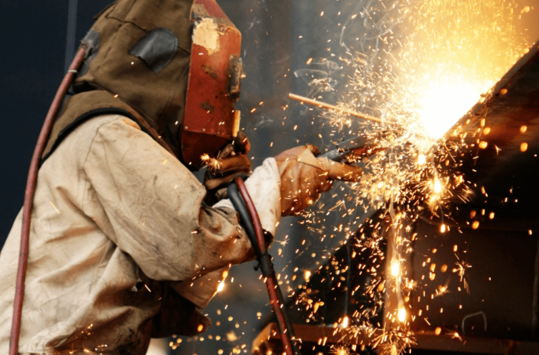
When the electric welding equipment catches fire, you should first switch off the power supply and then start extinguishing the fire. Before cutting off the power, you cannot use water or foam fire extinguishers to put out the fire, otherwise, it is easy to cause electric shock. You should use dry powder fire extinguishers, carbon dioxide fire extinguishers, carbon tetrachloride fire extinguishers or 1211 fire extinguishers to fight the fire. Dry powder fire extinguishers are not suitable for extinguishing fires in rotary DC welding machines.